Introduction
Most of the advanced materials, e. g., functional ceramics and high temperature materials are hard to machine. Grinding is widely used, and an important machining operation for producing modern equipment using advanced materials. At present, the percentage of machining cost would be about 80% or more of the total component cost in the industrialized world [1]. Silicon wafers are used for the production of most microchips. Various processes are required to make a silicon wafer from a single crystal ingot. Typical processes, lapping/ surface grinding, and polishing of silicon wafers consume a long time and a high cost [2]. In grinding process, damages on ground surfaces are not avoidable. For removing the damaged layer, heat treatments and etching processes are required [3]. Excessive forces during grinding process generate defects such as chipping or cracking. Grinding materials inevitably generates both brittle fractures and ductile flaws as the diamond abrasive grains cut into the specimen [4,5]. For conventional grinders, grinding depth and feeding rates are controlled. Forces on the grinding plane increase to generate an excess stress on sample surface, and defects on ground surfaces. Astute operators monitor vibration [6,7], sound [8], and acoustic emission [9-11] to estimate the grinding wheel conditions in conventional grinding systems. In this study, we propose a new grinding equipment to achieve defect-reduced machining. This advanced machining has constant-force-feeding system. Hence, table- feeding rate is altered depending on grinding conditions. The effects of grinding depth with grinding forces, table-feeding rate and specific grinding energy (SGE) on constant-force-feeding grinding system using Si wafer and sintered Al2O3 are evaluated.
Experimental Procedure
A newly developed constant-force-feeding grinding system is used in this study. Figure 1 shows the schematic diagram of the setup for newly developed grinding system.
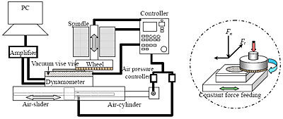
Figure 1. Schematic diagram of the constant-force-feeding grinding machine.
This system consists of an air sliding grinding-table, a vacuum vise and a cup-shaped diamond-grinding wheel. The vacuum vise is made by porous ceramic material, and machined to guarantee parallel surface between the vacuum vise and the grinding wheel surface for high flatness ground specimen. The specimen is placed on the porous vacuum vise without glue and air is evacuated to hold the specimen. This attachment will not cause any damage to the specimen. The grinding table is controlled by air cylinder and air slider for the constant-force-feeding system. In this study, 4 inch Silicon wafer and sintered Al2O3 (98.1-98.5% relative density and 25 mm X 50 mm) are used for evaluation of grinding abilities. Specimens are ground by a cup-shaped 600-grit grinding wheel (vitrified bond, 35-37% porosity with 30-40 μm diamond particles as abrasive grains, Nano TEM Co. Ltd., Nagaoka, Japan). Normal and tangential forces to the sample surface are measured by 3-component piezoelectric dynamometer (9257B. Kistler Corp.) during grinding. Effects of feeding depth (1 μm to 50 μm) per pass on grinding force and table feeding rate were evaluated. Table feeding rates from the period while grinding forces were active. The change of grinding wheel thickness between before and after grinding test is evaluated. Finally, the ground surface roughness and morphology are evaluated by confocal laser microscopy (LSM VK 8500. Keyence Corp.).
Results and Discussion
Figures 2 (a) and (b) show the relationship between grinding forces (normal force; Fn, tangential force; Ft) and table feeding rate (vf) versus feeding depth for sintered Al2O3 and Si wafer, respectively.
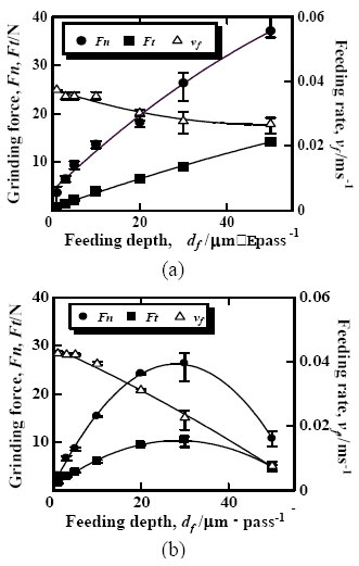
Figure 2. The influence of the various feeding depths on the grinding force (Tangential force; Ft, normal force; Fn) and table-feeding rate (vf). (a) Sintered Al2O3, (b) Si wafer.
Grinding forces of sintered Al2O3 increased continuously as the feeding depth increased. The grinding forces for Si wafer increased as Al2O3 for feeding depth to 30 μm/pass, and decreased as the feeding depth increased over 30 μm/pass. The cause of the decrease in forces is related to bonding strength between abrasive-grins and bonding matrix in the grinding wheels. Figure 3 shows the relationship between wearing ratio of grinding wheels versus feeding depth.
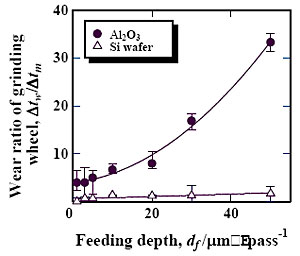
Figure 3. Wear ratio of grinding wheel increase as the feeding depth increase for sintered Al2O3. However, which is not the case of Si wafer.
The grinding wheel wear ratio was calculated by the following equation (1).
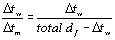 (1) (1)
Where Δtw is the change of grinding wheel thickness between before and after all the grinding, Δtm is effectively ground thickness, i. e., totally feeded depth (df), subtracted by grinding wheel change (Δtw). The grinding wheel wear for sintered Al2O3 increased rapidly as the feeding depth increased, but that for Si wafer did not change much. These results show the bonding strength of grinding wheels, e. g., bonding strength between abrasive-grains and bonding materials, or between bonding materials themselves is stronger than grinding Si wafer and weaker than sintered Al2O3. Therefore, grinding wheel surface was removed at the same time as ground sintered Al2O3 surface. For that reason grinding forces increased continuously; it is the effect of self-dressing to the grinding wheels. On the other hand, the used grinding wheels have enough bonding strength to grind Si wafer even at a feeding depth of 50 μm/pass; this feeding depth is larger than the abrasive-grain size of the grinding wheels. Therefore, Si wafer surface was removed and table-feeding speed decreased and grinding force decreased radically. The table-feeding rate decreased as feeding depth increased the grinding wheels did not under go the self-dressing effects, the edge of the abrasive-grains become dull, and contact area between wheel and specimen increased. It means that the feeding rate was altered depending on grinding conditions. These results demonstrate the assumption that constant-force-feeding grinding system controls feeding speed as grinding conditions varies.
Grinding forces between the grinding wheels and specimen are easily controlled. Therefore, excessive forces on ground surface were eliminated. Measured parameters allow to calculate the energy required to remove a given volume of specimen, i. e., specific grinding energy (SGE). The SGE was calculated by the ratio of the product of measured grinding force and wheel speed to the volumetric removal rate as shown in equation (2) [12].
 (2) (2)
Where Ft is tangential force, Vs is wheel velocity, and Vf is removal rate. Figure 4 show the relationship between SGE versus feeding depth. The SGE becomes constant at a feeding depth over 10 μm/pass Figure 5 shows the relationship between maximum roughness (Ry) versus feeding depth. The surface roughness does not change at various feeding depths. Moreover, this maximum surface roughness is the same value of pore size (Al2O3) and less than 4 μm (Si wafer) for any given feeding depth. These results also demonstrate that the constant-force-feeding grinding system does not generate excessive forces of ground surface.
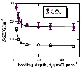
Figure 4: The specific grinding energy (SGE) becomes constant at a feeding depth over 10 µm/pass.
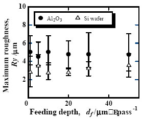
Figure 5: Similar maximum surface roughness (Ry) at different feeding depths (df).
Figure 6 shows SEM photograph of the side view of the silicon wafer (left) and sinterd-Al2O3 (right) before and after ground. Finally, we could grind the silicon wafer from 0.5 mm thickness to 40 μm and the sintered-Al2O3 from 1 mm thickness to 40 μm by only one-step of grinding in less than 50 min.
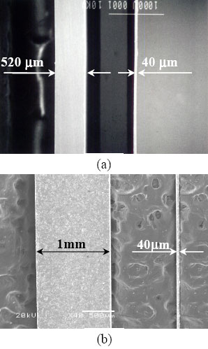
Figure 6. SEM photographs of the side view of the silicon wafer and sintered Al2O3 before (left) and after one-pass of ground (right). (a) Si wafer: One-pass grinding thinned to 40 µm from 520 µm thickness for only 50 min, (b) sintered Al2O3: 40 µm from 1mm thickness for 90min.
Conclusions
In this study, the constant-force-feeding grinding system was evaluated for reducing damages with high grinding rate for silicon wafer and sintered Al2O3. Grinding forces of sintered Al2O3 increased continuously as the feeding depth increased. The grinding force of Si wafer, however, decreased as the feeding depth increase over 30 μm/pass. The different in forces is caused by the relative differenced of bonding strength of grinding wheels with respect to the force required to remove Al2O3 or Si wafer. The grinding wheel wear for sintered Al2O3 increased rapidly as the feeding depth increased, but that for Si wafer did not change much. These results show the bonding strength of grinding wheels, e,. g., bonding strength between abrasive- grains and bonding materials, or between bonding materials themselves is stronger than grinding Si wafer and weaker than sintered Al2O3. Therefore, grinding wheel surface was removed at the same time as ground sintered Al2O3 surface. For that reason grinding forces increased continuously; it is the effect of self-dressing to the grinding wheels. On the other hand, the used grinding wheels have enough bonding strength to grind Si wafer even at a feeding depth of 50 μm/pass; this feeding depth is larger than the abrasive-grain size of the grinding wheels. The table-feeding rate decreased as feeding depth increased the grinding wheels did not under go the self-dressing effects, the edge of the abrasive-grains become dull, and contact area between wheel and specimen increased. It means that the feeding rate altered depending on grinding conditions and excessive force on ground surface was not created. The specific grinding energy becomes constant at a feeding depth over 10 μm/pass (Al2O3: about 17 GJ/m3, and Si wafer: about 7 GJ/m3). Maximum surface roughness (Ry) was evaluated by confocal laser microscopy. The maximum surface roughness does not change any feeding depths. Finally, we could grind the silicon wafer from 0.5 mm thickness to 40 μm and the sintered-Al2O3 from 1mm thickness to 40 μm by only one-step of grinding in less than 50 min.
Acknowledgement
The authors wish to express their gratitude to the Japanese government for partially supporting this work through the 21st Century Center of Excellency (COE) Program of the Ministry of Education, Culture, Sports, Science and Technology
References
1. J.Y. Shen, C.B. Luo, W.M. Zeng, X.P. Xu and Y.S. Gao, “Ceramics Grinding under the Condition of Constant Pressure”, J. of Materials Processing Technology, 129 (2002) 176-181.
2. H.K. Tonshoff, W. V. Schmieden, I. Inasaki, W. Koing and G. Spur, “Abrasive Machining of Silicon”, Annals of CIRP (Conf. Int. pour la Res. de Prod.), 39 [2] (1990) 621-630.
3. T. Fukami, H. Masumura, K. Suzuki and H. Kudo, “Method of Manufacturing Semiconductor Mirror Wafers”, European Patent Application, EP0782179A2, Bulletin (1997) 27.
4. S. Malkin and J. E. Ritter, “Grinding Mechanism and Strength Degradation for Ceramics”, ASME, J. of Engineering for Industry, 111 (1989) 167-173.
5. S. Malkin and T. W. Hwang, “Grinding Mechanism for Ceramics”, Annals of CIRP (Conf. Int. pour la Res. de Prod.), 45 [2] (1996) 569-580.
6. T. Shirakashi, W. Gong and T. Obikawa, “In-process Monitoring of Tool Damage by Active Method – Behavior of Damping Ratio with Tool Wear Development”, J. of the Jpn. Soc. for Precision Engin., 61 [12] (1995) 1750-1754.
7. M. E. R. Bonifacio and A. E. Diniz, “Correlating Tool Wear, Tool Life, Surface Roughness and Tool Vibration in Finish Turning with Coated Carbide”, Wear, 173 [1-2] (1994) 137-144.
8. J. H. Ahn, H. S. Lim, S. Takata and T. Sata, “Machining Process/Tool Wear Monitoring System Based on Real-Time Sound Recognition”, J. of the Jpn. Soc. for Precision Engineering, 60 [8] (1994) 1144-1148.
9. C. R. Heiple, S. H. Carpenter, D. L. Armentrout and A. P. McManigle, “Acoustic Emission from Single Point Machining-Source Mechanisms and Signal Changes with Tool Wear”, Materials Evaluation, 52 [2] (1993) 269-274.
10. H. Takeshita and I. Inasaki, “Monitoring of Milling Process with an Acoustic Emission Sensor”, J. of the Jpn. Soc. for Precision Engineering, 59 [2] (1993) 269-274.
11. A. E. Diniz, J. J. Liu and D. A. Dornfield, “Correlating Tool Life, Tool, Wear and Surface Roughness by Monitoring Acoustic Emission in Finishing Turning”, Wear, 152 (1992) 395-407.
12. A. Takata, “Kou-nouritsu Kou-kensakuhi Takoushitsu Daiyamondo Toishi no Kaihatsu”, Doctoral Dissertation of Nagaoka University of Technology, Japan (1998) (in Japanese).
Contact Details
|
Hyunjin Kim, Koji Matsumaru and Kozo Ishizaki
Nagaoka Gijutsu-Kagaku Daigaku
Nagaoka University of Technology
940-2188, Japan.
E-mail: [email protected]
|
Atsushi Takata
Nano-TEM Co. Ltd.
Shimogejo 1-485, Nagaoka, Niigata
940-0012, Japan
|
|