This article discusses the various control mechanisms for MEMS Coriolis Vibratory Gyroscopes (CVG), and how they can be applied with the commercial off-the-shelf HF2LI Lock-in Amplifier.
A MEMS gyroscope is a micro-machined inertial device that can be used to measure the angular rate of rotation or the angle of orientation. The principle relies on a vibrating structure that is suspended in a way that Coriolis forces can be detected as the mass experiences a rotation relative to the inertial space.
Lock-in amplifiers can efficiently sense these Coriolis forces. In addition, feedback control is generally used to enhance the vibration properties and improve the overall performance. In order to achieve highly accurate sensing, numerous control loops are run in parallel and the control infrastructure can become complex.
This article provides examples of practical implementations of closed-loop and open-loop control examples. How to perform a basic gyroscope drive-mode control using phase-locked loops (PLL) and automatic gain control (AGC) will be explained.
The drive-mode control is then combined with either closed-loop force-to-rebalance operation or open-loop sensing. Electro- mechanical amplitude modulation will also be explained.
All of the signals of interest in this scheme are amplitude modulated. By rejecting parasite effects, this can enhance the gyroscope performance.
The HF2LI provides a wide range of features, making it a powerful instrument for driving and characterizing accelerometers, vibratory gyroscopes, and other MEMS oscillating structures. The main features are built-in signal modulation and demodulation at many frequencies in parallel, PLLS, amplitude control, and PID controllers. The two 50 MHz low-noise signal input and output pairs enable control of the drive and the sense modes of gyroscope vibration (Figure 1).
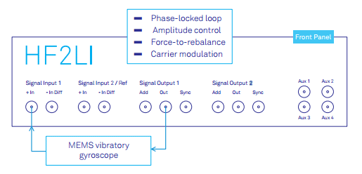
Figure 1. The Zurich Instruments HF2LI lock-in amplifier incorporates the infrastructure to perform basic resonator control as well as advanced gyroscope operation.
Overview of the HF2LI Lock-in Amplifier
A knowledge of the internal structure of the instrument is helpful to understand how the HF2LI digital lock-in amplifier is used for gyroscope applications.
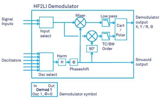
Figure 2. HF2LI demodulator schematic with the different settings, which are summarized in Table 1. The simplified symbol at the bottom is used in the schematics of this document.
The most important component of any lock-in amplifier is the demodulator that performs very narrow-band filtering of the signal of interest around a specific frequency. As a result of this demodulation, there is a precise measurement of the phase of the signal and the amplitude even when the signal is seemingly covered by noise.
Figure 2 shows the essential structures of the HF2LI demodulator. There is an oscillator input selector, a signal input selector, two low-pass filters, two mixers, and a cartesian-to-polar converter. The chosen input signal is multiplied by the normalized sine emitted by one of the six input oscillators, which operates at a defined frequency ω.
The sine may be harmoic of ω and it may be phase shifted before it is applied to the mixers. Two mixers are employed with 90º phase shift against each other to determine the in-phase and out-of-phase components of the input signal, enabling the calculation of the amplitude and the phase of the input signal at frequency ω.
The harmonic and phase shift settings impact the modulator output, and can be employed as an excitation signal to the setup.
Table 1 provides a summary of all settings of the HF2LI demodulator.
Table 1. Demodulator parameters
| Signal / parameter |
Description |
| Input select |
Each demodulator can be connected to either of the two signal inputs |
| Osc select |
Each demodulator can be connected to any of the six oscillators. |
| Harm |
Harmonic, usually "1". Frequency multiplication to demodulate higher harmonics |
| Phase shift ? |
Phaseshift between oscillator and input/output mixer |
| TC,BW |
Time constant or bandwidth of the low pass filter |
| Order |
Filter order from 1 to 8 |
| Demodulator |
X,Y, R, ? of the measured signal |
| Sinusoid Output |
Sinusoid signal that can be connected to any of the two signal outputs |
As can be seen in Figure 3, there are 8 dual-phase demodulators in the HF2LI. Two of these are employed for PLL operations, and users can configure six of them in the most flexible way.
With the input and output mixers, any demodulator input or output can be connected to any of the two physical input and outputs of the device. Signals from the different demodulators can be multiplied and added up by the output multiplexers. This allows signals from two or more modulator outputs to be combined.
Amplitude or frequency modulation and demodulation can be performed with the modulation option (HF2LI-MOD) in HF2LI. Using this modulation option, the oscillators that drive the demodulator of Figure 2 can be changed to make the demodulator perform an amplitude demodulation.
As can be seen in Figure 4, the oscillator signals applied to the demodulator 2 and 3 are now the sum and difference of the two frequencies.
As a result, a direct sideband demodulation of an amplitude modulated signal can be performed. For instance, a signal which has a carrier frequency of f1 = 52 kHz and an amplitude modulation frequency of f2 = f3= 2 kHz can directly be modulated at the sideband frequencies 52 + 2 kHz and 52 - 2 kHz.
Conventionally, two lock-in amplifiers in series were required to perform this operation. Also, one or both of the modulation and the carrier frequency in the HF2LI can be either controlled or fixed with a PLL. This enables direct sideband demodulation to be performed, while simultaneously running the resonator at its natural resonance frequency using a PLL.
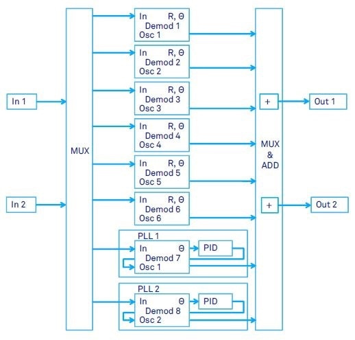
Figure 3. HF2LI input and output schematic showing 2 signal inputs, 2 signal generator outputs, 6 dual-phase demodulators and 2 phase-locked loops (shown schematic requires both HF2LI-PLL and HF2LI-MF option).
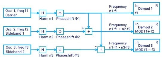
Figure 4. Schematic of three of the HF2LI demodulators with amplitude modulation applied. With the modulation option of the HF2LI, the user can define the carrier frequency f1 and the sideband frequencies f2 and f3 of the amplitude modulation. As a consequence, the demodulator 2 will run at the sum frequency f1+f2 and the demodulator 3 at the difference frequency f1-f2 (if no harmonics are used). This enables the direct demodulation of the signal at the sidebands f1+f2 and f1-f2. Any of the oscillator frequencies f1, f2 and f3 can be dynamic, thereby, e.g., controlled by a PLL or an external reference.
Gyroscope Operation
This section will discuss the most significant control and sensing modes for MEMS gyroscopes using the HF2LI lock-in amplifier. This should provide a better understanding into the basics of gyroscope control mechanisms and how to use the HF2LI lock-in amplifier for both control of drive- and sense-modes of vibration.
Drive Mode Control
Using a PLL, the oscillation of the vibratory gyroscope is maintained at resonance in the drive-mode control. A PID controller is used to keep the mechanical amplitude constant, or the performance of the CVG can degrad due to the temperature drift.
Figure 5 provides the basic setup. The input and output of the HF2LI is connected to the drive-mode of the gyroscope. It must be noted that additional circuitry may be required, which is not shown in the figure e.g. current-to-voltage conversions.
An offset (VOffset) is often applied to the drive signal for electrostatic actuation. This offset can be added with external circuitry or by the Add connector on the HF2LI front panel, which is very convenient.
The PLL locks to the resonance frequency of the drive mode. The modulator output of Demodulator 1 is used for the excitation of the drive-mode. The phase shift ΦX of the modulator is set to maximize amplitude of oscillations. The phase ΦX is generally 90 degrees unless the signal phases are significantly affected by the gyroscope’s electronics.
Consequently, this closes the PLL loop as PLL 1 controls the frequency of oscillator 1. Additionally, the excitation amplitude is kept constant by an AGC loop.
A PID controller is used by the AGC to compare and regulate the drive mode oscillation amplitude to a specific setpoint. The demodulator output X of the Demodulator 2 with zero phase shift operates as an input to the PID controller. It must be noted that the second demodulator must set the demodulation phase independently of the modulator output phase (Figure 2).
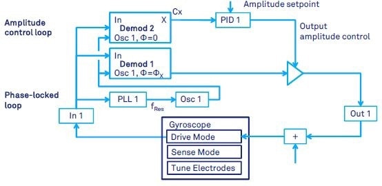
Figure 5. Gyroscope or general resonator drive-mode control by means of a phase locked loop and a PID controller for automatic gain control. The PLL keeps the resonator at its natural resonance frequency. The PID keeps fixed resonator amplitude.
Sense Mode Open-Loop Control
In the simplest gyroscope instruments, the gyroscope drive-mode control is applied as discussed in the previous section, and the sense-mode is implemented in open loop. This method is one of the basic operation principles and is used extensively. An example of this is found in (Prikhodko 2012) and in (Prikhodko 2013).
Figure 6 shows the input of Demodulator 3 connected to the gyroscope sense-mode output. Demodulator 3 utilizes Oscillator 1, which is controlled by the PLL. To ensure that the component Y of Demodulator 3 is the Coriolis output proportional to the angular rate, and that the component X of Demodulator 3 is the quadrature error, the demodulator phase shift ΦY is adjusted.
The phase ΦY is usually set by trial and error until component X is not sensitive to rotation (when gyroscope is in rotation). It can range between -90 degree to 90 degrees based on the mode-matching condition (difference between the natural frequencies of drive- and sense-mode).
The amplitude-decay time constant τy (Equation 5) limits the gyroscope response time to the input rotation, and this limits the bandwidth of the gyroscope (Lynch 1998). Force-to-rebalance control must be used to increase the bandwidth (reducing the response time) and remove the effect of the frequency mismatch Δω on the gyroscope scale-factor,
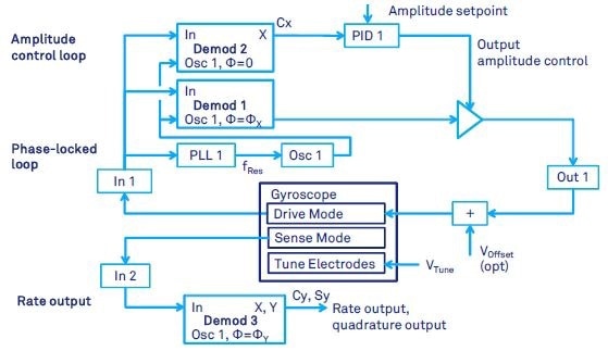
Figure 6. Gyroscope control with closed-loop drive-mode and open-loop sense-mode measurement. The drive mode is controlled by means of a PLL and an AGC. The gyroscope output is an oscillation in the sense mode which is measured by a demodulator running at the same frequency as the PLL of the drive-mode.
Force-to- Rebalance Control
(Lynch 1998) describes the force-to-rebalance (FTR) mode of operation for rate measuring gyroscope in detail. Four control loops for drive- and sense-modes of a MEMS Coriolis Vibratory Gyroscope can be seen in Figure 7. Specifically, two input signals from the gyroscope (from drive and sense mode) are demodulated to obtain in-phase and in-quadrature (out-of-phase) signals sx, cx, sy, cy (notations are conveniently adopted from (Lynch 1998)).
The signals cx and sx are the out-of-phase Y and in-phase X components of the demodulator outputs of the drive-mode vibration. Similarly, the signals sy and cy are the out-of-phase Y and in-phase X components of the sense-mode demodulator.
When demodulation phases ΦX and ΦY are set as explained in previous sections, the physical meaning of these signals are: cx stands for the drive-mode amplitude, sx stands for the drive-mode phase, cy stands for the Coriolis amplitude (proportional to the rotation rate), and sy stands for the quadrature error.
These four signals serve as the input for the four control loops, which includes a PLL. Although PID controllers are used, the differential term D is usually not employed. The control signals from the PID accumulate to obtain one drive output, which is fed back to the gyroscope for sense-mode control.
The drive-mode control is the same as discussed in the previous section. By regulating an amplitude of the modulator Output 2 from Demodulator 4 (with 90 degrees phase shift), the PID controller 2 maintains Demodulator 3’s output Y at zero.
Similarly by regulating an amplitude of the modulator Output 2 from Demodulator 2 (with 0 degree phase shift), PID controller 3 keeps Demodulator 3’s output X at zero.
The FTR mode extends the gyroscope’s bandwidth beyond the limitation of the open-loop sense-mode, which is generally restricted by the amplitude decay time constant. The P and I gains control the bandwidth of the FTR loop. The FTR scale-factor is more stable as it does not rely on the frequency mismatch (in contrast to the open-loop scale-factor).
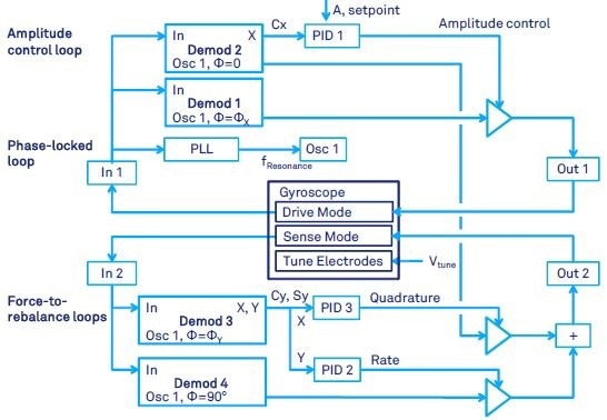
Figure 7. Gyroscope control with both closed-loop drive-mode and closed loop sense mode. This mode is usually called force-to rebalance (FTR). With FTR, the rate and quadrature output of the sense mode are suppressed by means of feedback control. The necessary feedback force is a measure of the rate of angular rotation.
Carrier Modulation
In gyroscope applications, a carrier frequency modulation scheme is used to enhance the detection sensitivity (Trusov 2007). The background noise and contributions from parasitic effects are rejected by carrier modulation.
The HF2LI is particularly suited for this task as it is the only digital lock-in amplifier with an adequate infrastructure for complete control of the drive and sense mode including carrier modulation.
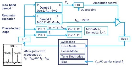
Figure 8. Gyroscope drive-mode control when the carrier modulation is employed. The gyroscope signal at resonance frequency fRes is amplitude modulated with carrier frequency fc. As a result, the signal of interest is shifted to the frequencies fc+fRes and fc-fRes. The shown setup (i) locks to the sideband fc+fRes by means of a PLL, (ii) demodulates directly the sideband at fc+fRes, (iii) computes the excitation frequency fRes from fc +fRes and fc by means of the MOD option, and (iv) excites the gyroscope drive mode at fRes with gain control (AGC).
In addition to the control loops presented earlier, a carrier signal at frequency fc (an order of magnitude higher than the gyroscope resonant motion) is used for separation from parasitic-capacitance feed through. Figure 8 shows how the demodulator will operate in this case.
This method is known as electromechanical amplitude modulation (EAM), and is used in e.g., (Prikhodko 2011, Prikhodko 2012). The implementation of this method requires side-band demodulation of gyroscope motion signals in both drive and sense directions, which in case of the quadruple-mass gyroscope (QMG) used in (Prikhodko 2011) is typically at 2 kHz modulation frequency and the carrier signal is chosen at 52 kHz.
As can be seen in Figures 8, 9 and 10, the 52 kHz carrier signal from a signal generator is fed to the gyro ground. While the first lock-in amplifier input is employed for drive-mode signal pick-off from the gyroscope, the second input is used for sense-mode signal read-out.
The first output is used to control the drive-mode, and the second output is used to control the sense-mode. Both modes generate output signals around the natural oscillation frequency of the gyroscope, which is around 2 kHz in this case.
The simultaneous control of three variables: cx (amplitude), cy (rate) and sy (quadrature) are essential for the closed-loop gyroscope operation. This is achieved using, three PID controllers (excluding the PLL), modulators producing feedback signals at the frequency of Oscillator 1 and three different phase shifts relative to each other.
Demodulator 3 measures the amplitude of the drive-mode oscillation and PID 1 controls it. Demodulator 6 measures the rate and quadrature of the sense-mode oscillation, and PID 2 and PID 3 control these two aspects, respectively.
If the demodulation phases for Demodulators 3 and 6 are set at zero and ΦY (explained in the previous section), the component X of Demodulator 3 is amplitude, the component Y of Demodulator 6 is rate, and the component X of Demodulator 6 is quadrature.
After demodulation, these three components are fed to PIDs that sustain the amplitude at a constant level, and the rate signal and the quadrature at zero. The outputs of PID outputs are modulated (i.e. by controlling the output amplitude of the oscillator signals) in order to form a feedback signal.
Negligible phase shifts are assumed in gyroscope’s front-end electronics, and the modulator output of Demodulator 2 with 90 degree phase shift is utilized for both rate and amplitude feedback. For quadrature nulling, the modulator output of Demodulator 5 with 0 degree phase shift is used. Finally, before the control signals are fed back into the gyroscope, the modulated outputs are summed up.
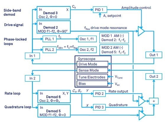
Figure 9. Gyroscope control with both closed-loop drive-mode and force-to-rebalance (FTR), when the carrier modulation is employed.
The schematic in Figure 9 assumes that there is a 90 degree phase shift between the applied force and the displacement at resonance, i.e. phase of the modulator output in Demodulator 2 is set to 90 degrees.
The schematic in Figure 10 can be implemented if this phase relationship is significantly affected by the gyroscope’s front-end electronics. Compared to AC quadrature nulling proposed in Figure 9, the quadrature correction can be achieved when DC voltage is applied to the dedicated gyroscope electrodes.
The output from PID 3 is fed back to quadrature tuning electrodes through the auxiliary output Aux 1, instead of feeding back a dynamic signal via the Output 2 (Figure 9). Doing this frees up the modulator output of Demodulator 2, which can be set to an arbitrary drive phase ΦX, at which the amplitude is maximum. The rate signal is now nulled by the modulator output of Demodulator 5 with modulation phase of 90 degrees.
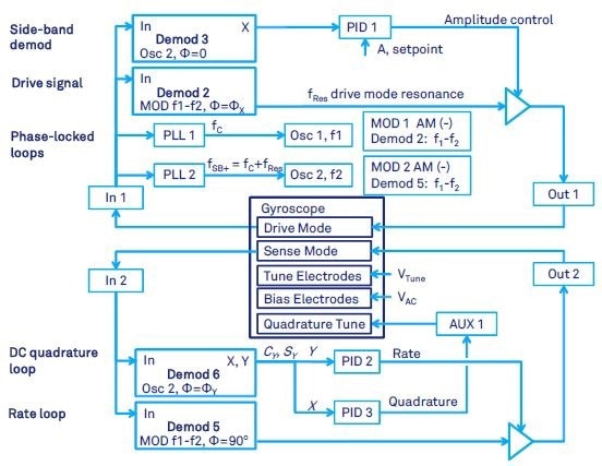
Figure 10. Gyroscope control with force-to-rebalance, carrier modulation and DC quadrature tuning.
Whole-Angle Readout
Unlike the rate measuring mode which has a predetermined axis of vibrations, free precession of the vibration pattern is required in the angle measuring mode (whole-angle). Using the whole-angle readout, a gyroscope can be operated without errors induced by a drive force.
In order to acquire the result in (Prikhodko 2011) and (Prikhodko 2013), the whole-angle readout depicted in Figure 10 was implemented. As shown in Chapter 5 in (Prikhodko 2013), the demodulated components cx, sx, cy, sy of the gyroscope’s pick-off signals are employed to compute the quadratic invariants. This was then used to find the immediate value of the precession angle θ(t) (Lynch 1998).
The whole-angle operation was used in open loop in (Prikhodko 2011). In order to start the vibrations, the gyroscope with 2 kHz operational frequency was electrostatically driven into the anti-phase resonant motion with a phase-locked loop, which was then suddenly turned off (indicated by the init switch in Figure 11).
In order to detect the oscillations of drive and sense modes and measure the precession angle, an EAM technique with sideband demodulation were used. The angle is computed offline from demodulated components cx, sx, cy, sy using a computer.
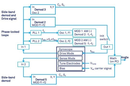
Figure 11. Gyroscope with carrier modulation in whole-angle mode with open loop readout.
Benefits for the HF2LI User
As multiple control loops must run in parallel, controlling vibratory gyroscopes is a complex task. Low noise electronics and high precision is essential to achieve maximum performance. As it combines the desired flexibility and precision in a single instrument, the HF2LI Lock-in Amplifier is ideal for gyroscope control.
Two low-noise inputs, two PLLs, two signal generators, four general purpose PID controllers, and six dual-phase lock-in amplifiers are available, and can be combined to achieve the desired functionality.
Numerous features used to control drive and sense mode vibrations with PLLs locked to the natural resonator frequency, quadrature control loop, force-to-rebalance control, and carrier modulation techniques for optimal performance are available in one HF2LI instrument. This makes the HF2LI the most accurate lock-in amplifier in terms of separating quadrature component from useful in-phase component (representing Coriolis response in CVG), that is available commercially.
In addition to the featured mentioned, the HF2LI provides a set of tools that can help an experimenter to analyze the measurement setup and quickly find the right parameters. All of these features are present in the user interface software.
- PLL Advisor: simulator ro find PLL parameters
- ZoomFFT: frequency spectrum around the resonance frequency. system disturbances such as ground issues and PLL stability can be debugged here.
- Oscilloscope: provides the raw input and output signal
- PID Tuner: simulator to detect PID parameters
- Spectroscope: offers the transient view of the amplitude and frequency signal. Helps to set the PID parameters and monitor the device at the time of the measurement.
- Sweeper: helps to find the resonance frequency and the appropriate phase shift required to set the PLL on the resonance
- Q-factor measurement through frequency sweeping or measurement of decay time
In addition to the HF2LI, Zurich Instruments also provides the UHFLI lock-in amplifier. Comprising a highly similar feature set to the HF2LI, the UHFLI can be operated at frequencies up to 600 MHz. The minimum time constant of the UHFLI is lower, while its PID controllers are faster. This makes it suitable for applications where a higher control bandwidth is required.
Acknowledgements
This application note was written together with Igor Prikhodko, former member of the Microsystems Laboratory of the University of California Irvine, now at Analog Devices, Inc., Wilmington, MA, USA.
We also would like to thank A. A. Trusov, A. M. Shkel, and S. A. Zotov from the MicroSystems Laboratory of the University of California Irvine for their insightful discussions regarding CVG and support.
References
[1] J. Bernstein et al. 1993. "A micromachined comb-drive tuning fork rate gyroscope," Proc IEEE Micro Electro Mechanical Systems Workshop (MEMS '93), Fort Lauderdale, pp. 143-148.
[2] J. A. Gregory, J. Y Cho, “Novel Mismatch Compensation Methods for Rate-Integrating Gyroscopes”, In Proc: Position, Location, and Navigation Symposium (IEEE/ION PLANS 2012), Myrtle Beach, SC, USA, 23 Apr - 26 Apr 2012, pp. 252- 258.
[3] P Greiff, B. Boxenhorn, T. King, L. Niles, "Silicon monolithic micromechanical gyroscope", Solid-State Sensors and Actuators, 1991. Digest of Technical Papers, TRANSDUCERS '91, pp.966-968, 24-27 Jun 1991.
[4] HF2 User Manual, Zurich Instruments AG, Zurich, Switzerland, www.zhinst.com.
[5] R. P Leland, “Mechanical-thermal noise in MEMS gyroscopes,” Sensors Journal, IEEE, 5(3), pp. 493-500, 2005.
[6] D. Lynch, “Coriolis Vibratory Gyros,” in Proc. of Symposium Gyro Technology, Stuttgart, Germany, 1998, pp. 1.0-1.14. (Reproduced as Annex B, Coriolis Vibratory Gyros, pp. 56-66 of IEEE Std. 1431-2004. IEEE Standard Specification Format Guide and Test Procedure of Coriolis Vibratory Gyros, IEEE Aerospace and Electronic Systems Society, 20 December, 2004.).
[7] I. P Prikhodko, S. Zotov, A. Trusov, and A. Shkel, “Foucault pendulum on a chip: Angle measuring silicon MEMS gyroscope,” in Proc. of IEEE Micro Electro Mechanical Systems Conference (MEMS 2011), Cancun, Mexico, Jan. 23-27, 201 1, pp. 161-164.
[8] I. F! Prikhodko, A. Trusov, and A. Shkel, “North-finding with 0.004 radian precision using a silicon MEMS quadruple mass gyroscope with Q-factor of 1 million,” in Proc. of IEEE Micro Electro Mechanical Systems Conference (MEMS 2012), Paris, France, Jan. 29-Feb. 2, 2012, pp. 164-167.
[9] I. P Prikhodko, “Development of a Self-Calibrated MEMS Gyrocompass for North-Finding and Tracking”, Dissertation, University of California Irvine, 2013.
[10] I.P Prikhodko, J.A. Gregory, C. Merritt, J.A. Geen, J. Chang, J. Bergeron, W. Clark, M.W. Judy, “In-Run Bias Self-Calibration for Low-Cost MEMS Vibratory Gyroscopes”, In Proc: Position, Location, and Navigation Symposium (IEEE/IONPLANS 2014), Monterey, CA, USA, 5 - 8 May 2014.
[11] A.M. Shkel, “Type I and Type II micromachined vibratory gyroscopes”, In Proc: Position, Location, and Navigation Symposium (IEEE/ION PLANS 2006), San Diego, CA, USA, 25-27 Apr. 2006, pp. 586-593.
[12] A. Trusov and A. Shkel, “A novel capacitive detection scheme with inherent self-calibration,” IEEE/ASME Journal of Micro electromechanical Systems, vol. 16, no. 6, pp. 1324-1333, Dec. 2007.
[13] A. Trusov et al. “Force Rebalance, Whole Angle, and Self-Calibration Mechanization of Silicon MEMS Quad Mass Gyro,” IEEE International Symposium on Inertial Sensors and Systems (IEEE ISISS 2014), Laguna Beach, CA, USA, Feb. 25 -26, 2014.
[14] J.-K. Woo, J. Y. Cho, C. Boyd, and K. Najafi, “Whole-Angle-Mode Micromachined Fused-Silica Birdbath Resonator Gyroscope (WA-BRG),” in Proc. of IEEE Micro Electro Mechanical Systems Conference (MEMS 2014), San Francisco, CA, USA, Jan. 26-30, 2014, pp. 20-23.
[15] H. Xie and G.K. Fedder, “Integrated MEMS Gyroscopes", Journal of Aerospace Engineering, Vol. 16 (2003), No. 2, p. 65-75.
[16] N. Yazdi, F Ayazi, K. Najafi, "Micromachined inertial sensors," Proceedings of the IEEE, vol.86, no.8, pp.1640-1659, Aug 1998.

This information has been sourced, reviewed and adapted from materials provided by Zurich Instruments.
For more information on this source, please visit Zurich Instruments.