The tunable microwave-frequency alternating current scanning tunneling microscope (ACSTM) can document local chemical information and local spectra on insulator surfaces, similar to what the traditional STM performs for semiconductors and metals.
Spectroscopy in the microwave frequency range provides previously unachievable measurements on conducting substrates, for example, the rotational spectroscopy of an individual adsorbed molecule.
Professor Paul Weiss developed the technology in the early 1990s. Weiss is the nano-pioneering director of the Weiss Group, a nanotechnology research unit of UCLA’s California NanoSystems Institute.
The ACSTM’s single-molecule measurement methods have offered previously unknown details about chemical behavior, comprising of observations of a single molecule’s motion on a surface, and even a single bond’s vibration within a molecule.
These types of measurements are essential to comprehend entities ranging from single atoms to the most complicated protein assemblies.
“We use molecular design, tailored syntheses, intermolecular interactions and selective chemistry to direct molecules into desired positions to create nanostructures, to connect functional molecules to the outside world, and to serve as test structures for measuring single or bundled molecules,” states David McMillan, lead technician at the Weiss Group.
“The ACSTM enables interactions within and between molecules to be designed, directed, measured, understood, and exploited.”
The group analyzes how these interactions impact electronic function, structure, dynamics, chemistry, and different characteristics.
These interactions can be utilized to form accurate molecular assemblies nanostructures and patterns, and to stabilize and control function.
Through an understanding of dynamics, interactions, and function at the smallest scales possible, the group aims to enhance synthetic systems at all scales.
Understanding ACSTM
The scanning tunneling microscope is established on quantum tunneling. When a conducting tip is moved very close to the surface to be analyzed, a bias (voltage difference) administered between the two enables electrons to move through the vacuum between them.
The consequent tunneling current is a function of applied voltage, tip position, and the local density of states of the sample.
Information is gathered by observing the current when the position of the tip scans across the surface. This is normally presented in image form.
STM can be a difficult method to use because very stable and clean surfaces are needed, along with sophisticated electronics, sharp tips, and excellent vibration control.
Good resolution is considered to be 0.01 nm depth resolution and 0.1 nm lateral resolution for an STM.
Utilizing microwaves reflected from the surface, microwave throughput attenuation, and the harmonics of the microwaves created by the tunnel junction, ACSTMs probe the chemistry of insulator surfaces.
They analyze photons generated from the tunneling junction and excited by the tunneling electrons. This provides enormous benefits in spatial resolution because the photons only come from the molecules or atoms through which the electrons are tunneling.
Testing has demonstrated how harmonic amplitudes in nonlinear spectroscopy with the ACSTM can be understood in terms of charging, electronic structure, and molecular motions.
The Weiss Group has employed these nonlinearities to investigate the electronic energies of insulator surface states.
Vibration Isolation
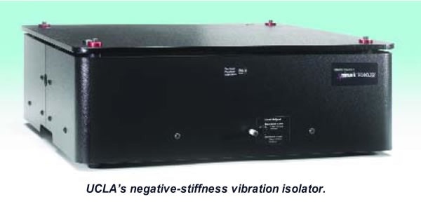
The ACSTM must be located in a highly stable operating environment to achieve the nanolevel spectroscopic and chemical data sets. “The lab was using almost exclusively optical tables on pneumatic isolation,” states McMillan.
“One of our big problems has been space constraint. We needed smaller pneumatic optical tables to fit. But as the air tables get smaller, their vibration isolation performance diminishes.”
The laboratory was sometimes moved to alternate locations at UCLA, which meant that space was not the only challenge.
The laboratory was on the sixth floor of a building with a steel structure in 2009, which had extensive movement challenges and produced low-frequency vibrations.
“We brought in an active vibration isolation unit to test, as well as a negative-stiffness system,” describes McMillan. “We compared the two systems, and the negative-stiffness system performed better with the frequencies of our concern, which were the lower frequencies caused by the movements of the building, between 10 and 24 Hertz.”
McMillan was initially intrigued by the negative-stiffness isolator due to reports that guaranteed very good low-frequency vibration isolation in a small footprint, making it much simpler to position in a compact box for thermal stability.
“I put it on a cyclic accelerometer and it performed outstandingly,” McMillan adds. “Much better than any other vibration isolation we had used before.”
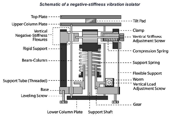
In negative-stiffness vibration isolation, vertical-motion isolation is offered by a stiff spring that holds weight in combination with a negative-stiffness mechanism.
The net vertical stiffness is made very low without influencing the static load-supporting ability of the spring. Beam-columns connected in series with the vertical-motion isolator offer horizontal-motion isolation.
A beam-column performs like a spring and a negative-stiffness mechanism. The outcome is a compact passive isolator with the capability of very low horizontal and vertical natural frequencies and very high internal structural frequencies.
The isolator brings 0.5 Hz horizontal isolation, and 0.5 Hz vertical isolation, utilizing an entirely passive mechanical system where no electricity or air is needed.
Isolation starts at around 0.7 Hz and enhances with an increase in the vibration frequency for an isolation system with a 0.5 Hz natural frequency. The natural frequency is more frequently employed to describe the performance of the system.
Negative-stiffness isolators resonate at 0.5 Hz. There is essentially no energy present at this frequency. It would be highly unlikely to locate a significant vibration at 0.5 Hz. Vibrations with frequencies over 0.7 Hz are quickly attenuated with a growth of frequency.
Air tables as vibration isolation systems provide restricted isolation vertically and less isolation horizontally. They can worsen issues with vibration isolation because they have a resonant frequency that can be equal to that of floor vibrations.
Instead of reducing vibrations, air tables will amplify them in a normal range of 2 to 7 Hz due to the natural frequencies at which the tables resonate.
All isolators will amplify at their resonant frequency, and then they will begin isolating. Any vibrations in that resonant frequency range could be amplified along with not being attenuated in the case of air tables.
Transmissibility with negative-stiffness isolators is significantly optimized over air systems. Transmissibility is a measure of the vibrations that are transmitted through the isolator in relation to the input vibrations.
When adjusted to 0.5 Hz, the negative-stiffness isolators attain a 93% isolation efficiency at 2 Hz, 99% at 5 Hz, and 99.7% at 10 Hz.
“Over the past four years, we have put six negative-stiffness isolation systems into the lab,” states McMillan. “And since, we have relocated into quarters with less movement. Although we do still have some air tables in use, our staff and graduate students prefer the negative-stiffness isolators.”
Acknowledgments
Produced from materials originally authored by Patrick Roberts from Minus K.

This information has been sourced, reviewed, and adapted from materials provided by Minus K Technology.
For more information on this source, please visit Minus K Technology.