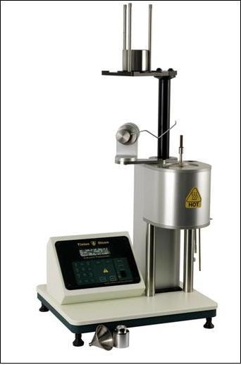
The Melt Flow Index (MFI), also known as the Melt Flow Rate (MFR), of a resin is a materials property test used in the plastics industry. The test measures the melt flow properties of resins (in g/10 min) at a particular shear stress (related to applied load) and temperature. The test is done with an extrusion plastometer, which is often referred to as a melt indexer. It is used to test virgin, compounded, and post-process thermoplastics.
MFI Test Standards
The two main MFI test standards are ASTM D1238 - “Standard Test Method for Melt Flow Rates of Thermoplastics by Extrusion Plastometer” and ISO1133 – “Determination of the Melt Mass-Flow Rate (MFR) and Melt Volume-Flow Rate (MVR) of Thermoplastics”. Both the test standards measure the same property but even slight procedural and equipment differences may provide different results. Both offer a manual method (Procedure A or Method A) and both offer an automatic timed flow measurement (Procedure B or Method B). Theoretically, both methods, if done properly will result in identical test results.
Guidelines for Choosing the Best Method
There is no clear-cut reason to prove which method is ideal for a particular organization; however there are certain guidelines that can be used to make a choice.
Procedure A is highly useful for organizations that test infrequently, utilise a wide range of materials, use a range of additives in their materials, or use regrind/recycled material.
Procedure B needs a “melt density” value and is ideal for organizations that test the same material several times over and want to reduce the chance for operator error. Some organizations may find that the alternative Melt Volume Flow Rate (MVR) procedure, offered by both standards more useful.
Factors that Affect Test Accuracy
Irrespective of the method chosen, two organizations may test the same material and obtain two different test results, wondering why the difference arose.
The precision and accuracy of a test are affected by a range of factors that include the following:
- The melt indexer needs to be in good working order
- The machine must have been calibrated by a certified metrologist, checking temperature, physical dimensions, and distance and time measurement accuracy
- The machine cleanliness needs to be maintained
- The technicians must be properly trained and use the same testing technique
- Testing procedures and requirements need to be closely followed by periodic testing of standard reference material (SRM) or control materials.
Hence it is important to examine the actual industry test standards. A trouble shooting guide is offered by ASTM D 1238 in the appendix of the document and certain salient features are highlighted below.
Standard Reference Materials & Proficiency Testing
A Standard Reference Material (SRM) is used by certain labs to crosscheck MFR test results. There is a restricted supply of certain materials available from national metrological standards bureaus such as the NIST in the United States but they tend to be expensive, and only offer an indication of verification for that particular material. It also raises the question whether the material is being used to test the machine or the machine is being used to test the material.
Certain labs choose to participate in Proficiency Testing Programs (PTP). Participation is voluntary and the programs charge a fee, but they provide a standard to compare how one’s testing practices stand with other participants. ASTM and Collaborative Testing Service are two vendors offering PTP services although, there may be other programs available.
The range of factors contributing to questionable Melt Flow Index test results is wide and deep. By being aware of each one, adhering closely to test procedures, maintaining the equipment, and following overall good testing practices, accuracy can be improved and ensure that small problems do not become big.
Equipment Issues that Affect Test Results
In order to ensure good test results, it is important that the testing machine and auxiliary equipment such as scales and micrometers are verified using equipment traceable to national metrological standards.
Certain measures that need to be taken are listed below:
- The verification procedure will check the machine dimensions, temperature control and distance measuring devices installed on the machine, for conformance to the relevant test standard.
- The frequency of the verification is determined by an organization’s quality program. Annual calibration is a common practice within the industry but regular inspection of the critical components of the test instrument must be done, especially for consumable items that include dies, piston rods, and piston feet. These should be replaced when required.
- Before conducting any tests, a visual inspection of all components of the testing machine shoud be carried out. The furnace of the instrument, which contains a heated metal cylinder with a defined bore, is leveled using equipment typically supplied by the equipment manufacturer.
- The equipment must be located in an area free from vibration and excessive air currents. Dimensional checks are to be made when the machine is cold.
- The test machine components must be cleaned after every test. No residue from prior tests must remain on the surfaces of the metal parts involved in the test. These surfaces are cleaned with cotton patches and cloth and/or a brass brush. Solvents are usually not needed or recommended.
- The barrel finish must be mirror-like and free of rust, scratches, and imperfections. The barrel is cleaned by repeated swabbing with a cotton cleaning patch using tools normally provided by the equipment manufacturer. Some material is a little more difficult to clean and may require the use of a brass brush to ensure a clean surface. After cleaning the barrel, a clean die must fall to the bottom of the barrel and make an audible “click.”
- The die outer surface is cleaned with a cotton cloth and the die bore is cleaned using a drill and/or a brush. The bore diameter, defined in D1238 as 2.0904 to 2.1006 mm (0.0823 to 0.0827”), must be periodically checked with a go/no-go gage. The die must be visually inspected to make sure that the entrance of the bore is not rounded or chipped. If the die fails the go/ no-go check or is damaged, discard it and replace it with a new, conforming die.
- The piston rod is normally cleaned with a cotton cloth but use of a brass brush may be needed for certain materials. The piston guide (if present) must slide freely on the piston rod. It is essential to periodically verify if the piston is straight and that the leading edge of the piston foot is sharp and free of burrs or damage that would cause it to rub against the barrel wall. The foot diameter when measured with a micrometer — must be 9.4676 to 9.4818 mm (0.3727 to 0.3733”).
Procedural Issues that Affect Test Results
Precision and accuracy can also be affected by procedural factors. Test conditions for test temperature and test load vary by material. Some materials have several test conditions. It is essential that comparative tests are performed using the same test conditions. Test conditions for most materials can be found in Table 3 of ASTM D1238.
Certain procedural issues that need to be taken care of include the following:
- Moisture content can be a large variable for some materials that include ABS, PMMA, PET, and Nylon. These resins must be dried in a suitable oven under controlled conditions before testing; some materials need to be dried under an N2 purge.
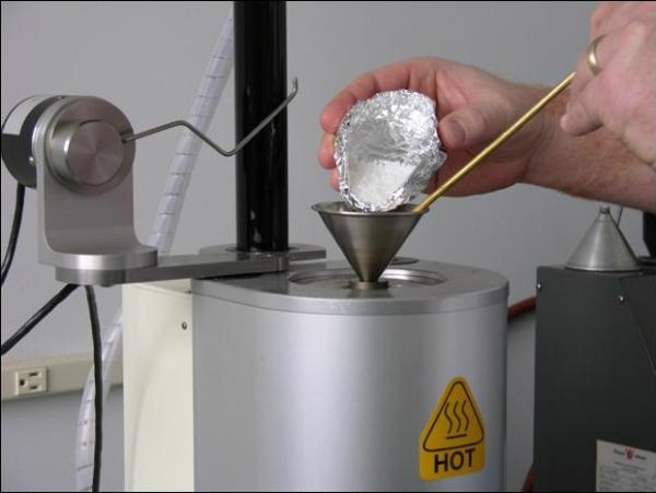
- Variations in sample mass and sample charging technique can affect test results of certain materials. Use of a tool to pack material into the bore during the charging process is common, but it can result in variations in test results for some materials if multiple machine operators are involved in the testing process because the amount of force used to pack the material often varies with operators.
- Similarly, the practice of purging excess material from the bore is normally used to move the piston closer to the starting point of the test and can be a source of variation in the test procedure.
- When the bottom of the piston foot is 46 +/- 2 mm from the top of die, a proper test is commenced. The piston foot is required to reach that point within 420 +/- 30 seconds after the material charging has been completed. A preheat time is needed to remove trapped air, ensure the material is sufficiently and uniformly melted, and that the temperature of the material in the bore stabilizes to within +/-0.2°C of the set point before the start of the test.
- A preferable alternative to packing the material purging is to use trial and error to measure the optimum amount of material to be charged in the bore, based on the expected flow rate, which will result in the test beginning at the proper time.
- It is common to weigh the material prior to charging or use a volume reference when charging the bore.
- The test load needs to be unloaded from the piston or its travel needs to be stopped during the preheat period in order to meet the preheat and start test requirements. It may also be essential to plug the orifice to prevent the material from running out completely before test commencement.
Procedure A Tests
Extrudate cutting technique can be a factor in Procedure A tests. A spatula or a similar cutting tool can be used to cut the material as it extrudes from the die at specific intervals. The extruded material must be cut at the exit of the die. It is important to cut accurately to obtain desired results. Procedure A can be used with materials that have flow rates up to 50 g/10 min. One must note that there are chances of error because of manual cutting at increased melt flow values. The first cut beginning at 46 +/- 2 mm is the reportable test result. Making successive cuts and then averaging them is not acceptable.
Procedure B Tests
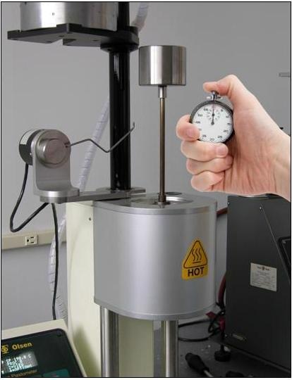
For Procedure B tests, permissible piston travel distances are 6.35 mm (1/4”) to 25.4 mm (1”). The operator chooses the distance based on the expected flow rate. The ¼” travel is used for low flow materials, while the 1” travel is used for higher flow rates.
As with Procedure A, the first measurement of a Procedure B test is considered to be the reportable test result. However, several modern testing instruments are equipped with an encoder based measuring device that will allow the user to divide up the specified travel distance into discrete “captures” and then average the captures to obtain the reportable test result. This practice is acceptable as long as the specified distances are used.
Procedure B requires the use of a melt density value, which is the density of the material when it is in its molten state. The melt density is a multiplier that converts volume back into a mass value. ASTM D1238 Table 4 lists generic melt density factors for virgin PP and PE. These factors will change with additives and processing so it is more precise to measure the actual melt density of the specific resin being tested. Procedure A and Procedure B test can be combined to give both weight and volume data, which allows the calculation of melt density.
Conclusions
In case you are suspicious of the melt flow data you have obtained, there are plenty of options for checking and updating equipment, examining procedures, and comparing results with those obtained by others. There is a high likelihood that answers to variances will be easily tracked down with some good old-fashioned detective work.

This information has been sourced, reviewed and adapted from materials provided by Tinius Olsen.
For more information on this source, please visit Tinius Olsen.