AO devices consist of a piezoelectric transducer and a suitable AO crystal cell (Bragg cell) coupled together. An ultrasound radio-frequency (RF) signal generates an acoustic wave inside the piezoelectric transducer. Further, this wave passes through the AO cell and acts like phase gratings for an incident laser beam.
As a result, the laser beam is diffracted at a specific angle of incidence. This interaction between acoustic gratings and the laser beam is physical in nature and is used for deflection, modulation, and spectral and spatial filtration of electromagnetic waves.
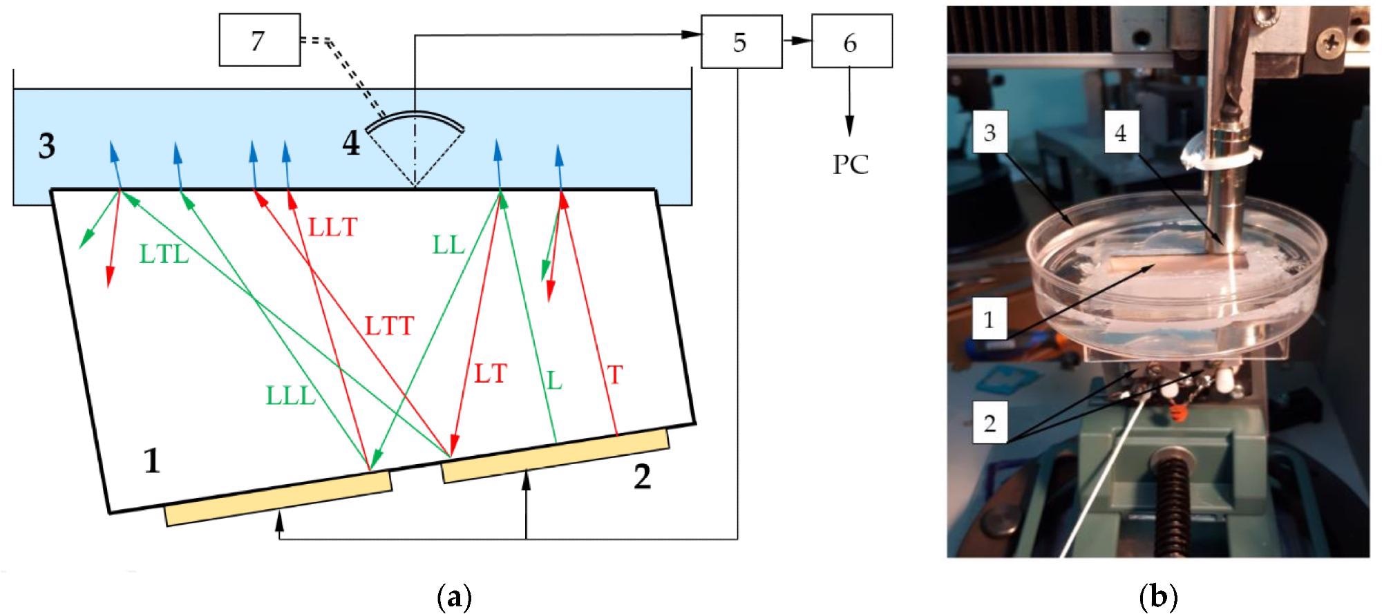
Scheme (a) and appearance (b) of the experimental setup: 1—AO cell; 2—emitting piezotransducer; 3—cuvette with immersion liquid; 4—receiving piezotransducer; 5—pulser-receiver; 6—analog-to-digital converter; 7—motorized translator. Green and red arrows show longitudinal (L) and transverse (T) waves propagating in AO cell, blue arrows correspond to longitudinal waves in liquid. Image Credit: Titov, S et al., Materials
Some commonly used AO materials are germanium (Ge) crystal, doped-glass, tellurium oxide (TeO2), fused silica or quartz (SiO2), arsenic sulfide (As2S3), lead molybdenum oxide (PbMoO4), and germanium arsenic selenide (Ge33As12Se55). All these materials are either used in glass form or crystal form. Moreover, they have different optimum optical ranges for AO applications.
The induced acoustic field inside the AO cell inevitably suffers from attenuation, divergence, walk-off, and reflection at the AO facet, due to heat generation, crystal inhomogeneity, and inner defects. Hence, proper examination of the structure of induced acoustic fields is essential for certification, and it gives a clear picture of the mismatch between theoretical and experimental performances of AO devices.
Imaging of lower frequency acoustic waves in AO devices has been performed using interferometric and holographic techniques. These techniques use a digital camera to record the diffracted laser beam, which depends on the frequency of the acoustic wave. Thus, the digital camera cannot record the output signal of very high-frequency AO devices. In laser beam scanning techniques, the diameter of the laser beam should be smaller than the wavelength of the acoustic wave, which means, it can be applied only for low-frequency acoustic fields.
About the Study
In this study, researchers used an immersion ultrasonic transducer and fused quartz as an AO modulator to investigate the modes, amplitudes, and propagation trajectories of ultrasonic waves inside the AO modulator.
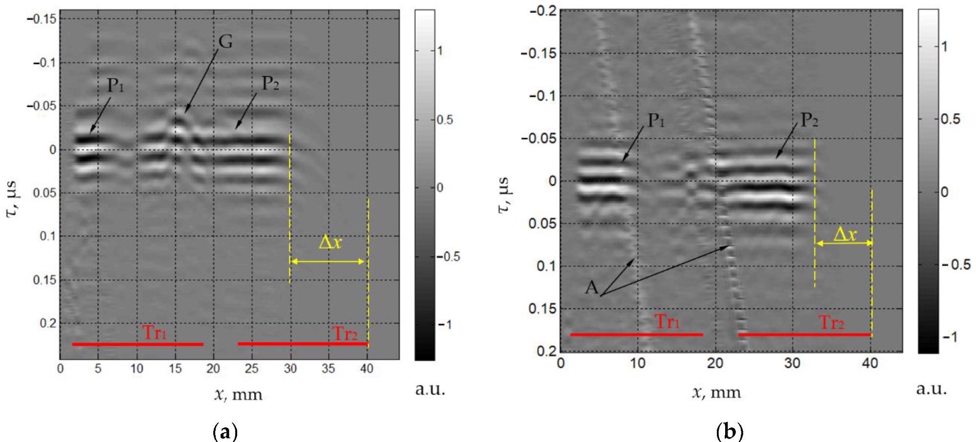
Measured spatio-temporal signals SLLL(x,τ) (a) and SLTT(x,τ) (b). Image Credit: Titov, S et al., Materials
The AO cell had a straight prism shape with a thickness of 12 mm. For isotropic interaction, longitudinal acoustic waves were generated in a lithium niobate transducer, which was attached to the bottom of the AO cell. Additionally, the upper plane of the cell was inclined at an angle of 6.5⁰ to prevent the formation of standing acoustic waves.
The mean RF was 50 MHz with a scanning range of 30 MHz. The upper plane of the AO cell was placed underwater using a cuvette. The second piezotransducer was placed at the quartz-water interface to record the spatial distribution of the waves. A pulse laser and an analog-to-digital converter were used at a resolution of 12 bits and a sampling rate of 500 MHz.
Observations
The direct transverse wave had a significant relative amplitude of 0.078. Moreover, this unwanted transverse wave propagates in the same direction as that of the longitudinal waves and cannot be attenuated by the absorber. Hence, the presence of transverse waves along with longitudinal waves cannot be undermined during calculations.
Furthermore, the longitudinal wave with an amplitude of 0.77 was the largest reflected wave. The transverse waves generated at the upper interface due to the mode conversion of the incident longitudinal wave were much weaker, therefore they were ignored.
The amplitudes of the direct waves did not change, whereas the amplitudes of reflected waves became smaller in the presence of the absorber. The velocities of longitudinal and transverse waves were 2650 m/s and 1100 m/s, respectively, for a solid absorber medium with a density of 1150 kg/m3. Also, the amplitudes of the reflected waves were small but not negligible.
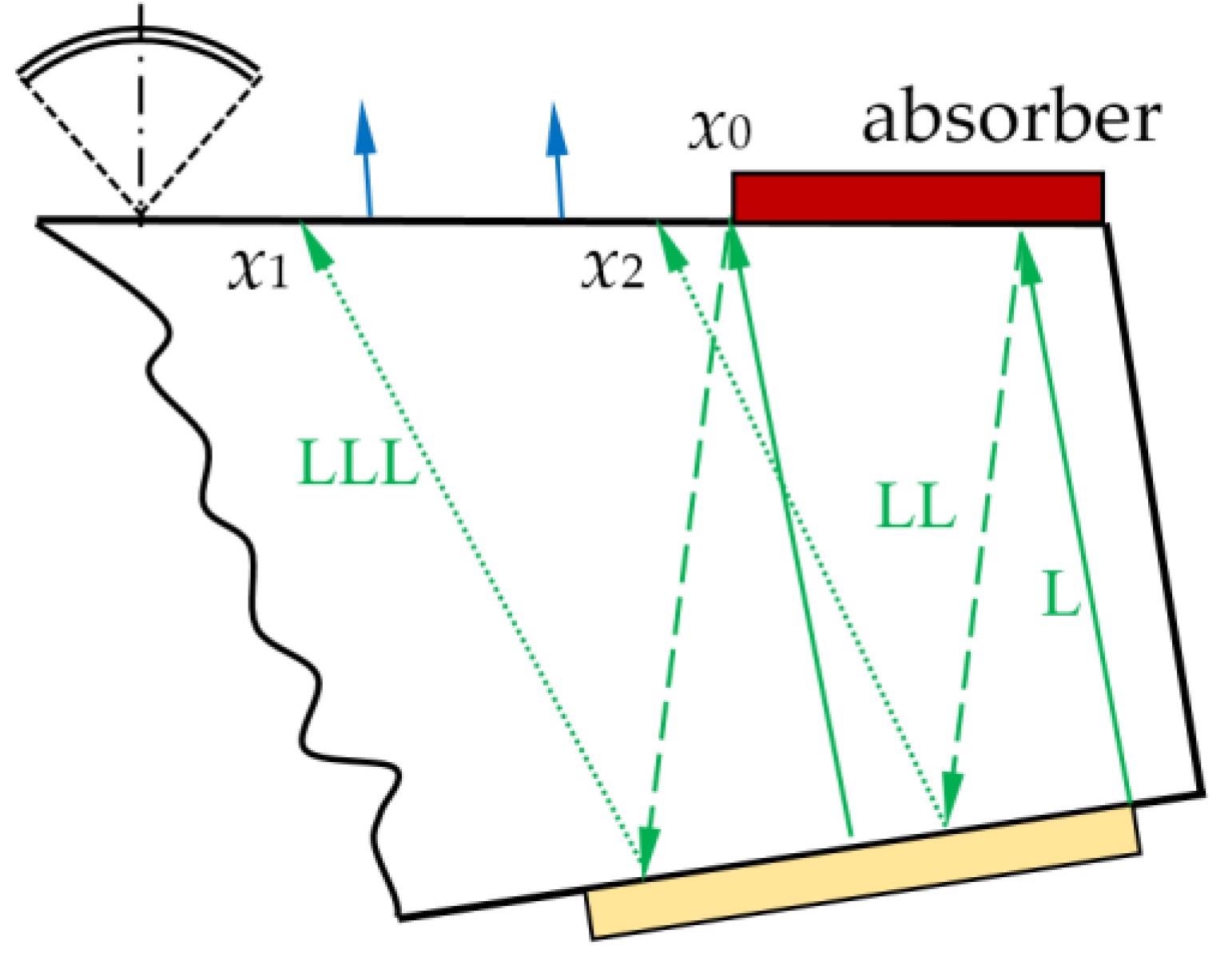
Ray propagation in AO cell with absorber. Image Credit: Titov, S et al., Materials
Conclusions
To conclude, the researchers of this study used impulse acoustic microscopy to characterize the ultrasonic acoustic fields in fused quartz AO cells. This method was ideal for systems with multiple reflections owing to a significant match between the theoretical and experimental values of reflection amplitudes and reflection coefficients.
Moreover, it detected the presence of unwanted transverse waves accurately. Hence, it is a promising method for theoretical estimation and modeling of the structure of acoustic fields in AO devices.
Disclaimer: The views expressed here are those of the author expressed in their private capacity and do not necessarily represent the views of AZoM.com Limited T/A AZoNetwork the owner and operator of this website. This disclaimer forms part of the Terms and conditions of use of this website.