Piezoresponse force microscopy is a non-destructive and extremely powerful analytical technique that has found increasing application in a wide range of fields over the past couple of decades.
This analytical technique has provided profound insights into local disorder potentials and magnetoelectric couplings, as well as several other behaviors and properties of materials and systems.
PFM can be used in combination with other analytical methods to explore multiple functional properties of materials. This analytical technique has been applied in areas such as biological systems, fuel cells, and battery research in recent years. Indeed, this analytical technique is fast becoming a cornerstone of many fields of research, providing intimate insights into material properties.
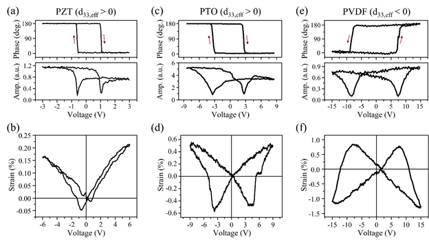
(a,c,e) PFM phase (top panel) and amplitude (bottom panel) and (b,d,f) quasi-static strain loops in IrO2/PZT (200 nm)/Pt capacitor (a,b), PTO (90 nm)/SrRuO3/KTaO3 thin film (c,d) and PVDF (22 nm)/Pt/Si thin film (e,f). The strain loops show that the d33,eff is positive for PZT and PTO and negative for PVDF. A clear correlation between the sense of rotation in the PFM phase signal and the sign of the d33,eff can be observed. The PFM hysteresis loops were acquired in the bias-off mode below the resonance frequency and the phase loops had
the same initial phase offsets for all three samples. Image Credit: Buragohain, P et al., Advanced Materials
In piezoelectrically active materials, electrical fields cause them to deform. Although the physical principle of piezoresponse force microscopy may appear straightforward, issues such as thermal effects, electrostatic signals, and electrochemical reactions can complicate the interpretation of PFM signals.
Quantifying PFM amplitude and phase signal is a key ongoing challenge in research currently due to the complex interplay of factors. For this reason, many current studies use uncalibrated measurements to provide quantitative assessments of physical parameters such as domain wall roughness and local coercive fields.
Using uncalibrated measurements is problematic, especially when comparing the analysis of similar materials. Calibrated, artifact-free PFM signals are particularly useful for exploring ferroelectric material piezoelectric properties. For this reason, there is an urgent need to improve methods for calibrating PFM signal measurements. Doing so will have important implications for multiple research fields.
The Paper
The main focus of the new paper is the quantification of phase signals. Two different approaches are utilized by the authors, with these approaches used to investigate the reported variations in the longitudinal coefficient’s sign in emerging HfO2-based ferroelectric materials.
The two approaches employed in the research correct the reported phase offset problem in conventional OBD methods, which are commonly employed in AFM measurements. Reference samples are employed in the first approach, whilst the second approach detects cantilever-sample interactions to overcome these phase offsets, which are parasitic in nature.
Piezoresponse force microscopy measurements were conducted using a commercial AFM system in the resonance DART mode. Single crystalline diamond tips were used to perform the majority of experiments on prepared ferroelectric thin-film capacitor samples. A stiff cantilever was used to study the electrostatic effect’s contribution.
Bias was applied to the top electrode to provide capacitor geometry measurements with a grounded bottom electrode. Bare surface measurements involved the application of bias to the conductive tip with a grounded bottom electrode. Actual sample displacement was elucidated by converting the deflection signal by calibrating the sensitivity of the cantilever optical lever. Dividing the measured displacement by sample thickness produced strain values.
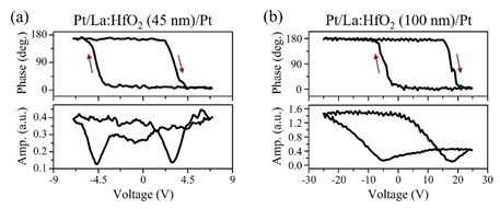
(a, b) Bias-off PFM phase (top panel) and amplitude (bottom panel) loops obtained on Pt/La:HfO2/Pt capacitors with the La:HfO2 film thickness of 45 nm (a) and 100 nm (b). The clockwise rotation of the phase signal shows that the d33,eff is positive in both samples. The loops shown in (a) were obtained after wake-up, while the loops in (b) were obtained in the pristine state. Image Credit: Buragohain, P et al., Advanced Materials
Study Conclusions
Applying the two methodologies revealed interesting variations in piezoelectric coefficients in thin-film ferroelectric capacitors. The piezoelectric properties of these materials are sensitive to their thickness, electrodes, and deposition methods. In single devices s wide variation in this coefficient sign change can occur.
The efficaciousness of a properly calibrated PFM signal for identifying local piezoelectric coefficients was demonstrated in the paper. Additionally, the research provides strategies for calibrating the raw phase signal. Using a reference sample or cantilever-sample electrostatic interaction features can efficiently identify parasitic phase offsets in these materials.
Specifically, the piezoelectric coefficient signs in the studied materials can display uniform positivity or negativity, and there can be a mixture of local negative and positive responses in ferroelectric capacitors. To clarify the physical mechanisms which govern this phenomenon, further structural studies will be necessary.
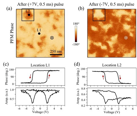
Coexistence of regions with positive and negative d33,eff in IrOx/La:HfO2 (20 nm)/IrOx capacitors. (a,b) PFM phase images after application of (+7 V, 0.5 ms) pulse (a), and (-7 V. 0.5 ms) pulse (b). The square in (a,b) represents a region with positive d33,eff. (c,d). Representative bias-off hysteresis loops obtained in location L1 (c) and in location L2 (d). Image Credit: Buragohain, P et al., Advanced Materials
Overall, and perhaps most importantly, the study has demonstrated the suitability of piezoresponse force microscopy with properly calibrated phase signals for determining and revealing nanoscale insights into piezoelectric behavior spatial variations. This overcomes the issues with conventional macroscopic measurements, which cannot provide these valuable insights.
The study provides guidelines for quantifying phase signals in piezoresponse force microscopy, which will improve future studies on emerging classes of materials such as hafnia-based ferroelectrics and will benefit multiple key industries. Whilst there are still challenges associated with this method, current research such as this paper is highly promising.
Further Reading
Buragohain, P et al. (2022) Quantification of the electromechanical measurements by piezoresponse force microscopy Advanced Materials [online] onlinelibrary.wiley.com. Available at: https://doi.org/10.1002/adma.202206237
Disclaimer: The views expressed here are those of the author expressed in their private capacity and do not necessarily represent the views of AZoM.com Limited T/A AZoNetwork the owner and operator of this website. This disclaimer forms part of the Terms and conditions of use of this website.