Mar 21 2002

Fernando Blanco Calzada / Shutterstock
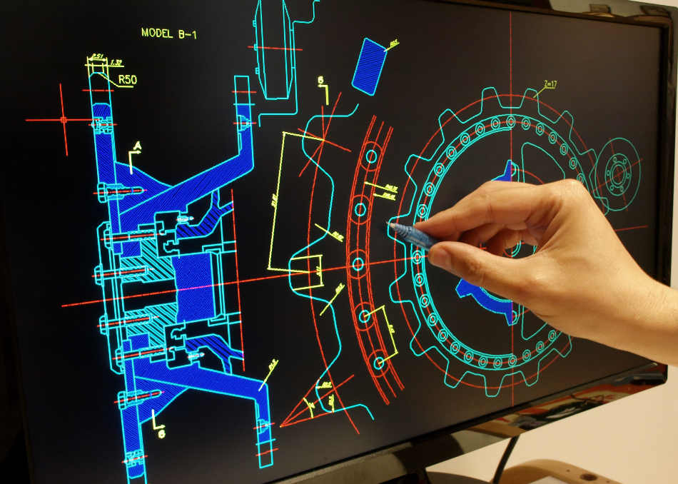
Product development cycles have decreased considerably with the growing use of Computer-Aided Design (CAD). Solid modeling used with approaches such as mechanical simulation and finite element analysis has considerably decreased the cost and time scale of product development in a broad range of engineering areas.
A three-dimensional (3D) rendered computer image is an excellent way of showing the details of the finished item. However, the demand for true solid product prototypes is growing.
Uses for Prototypes
Prototypes have a range of applications:
- Marketing tools
- Product visualization
- Functional testing
- Assessment of form and fit
- Short-run production cycles
- Proving production processes
Advantages of Rapid Prototyping
The traditional prototyping routes are expensive, inflexible, and add substantial cost to the product development cycle. However, the application of rapid prototyping methods and Computer-Aided Manufacturing (CAM) processes such as CNC machining has demonstrated the potential to enhance the process.
Commercial Rapid Prototyping
Commercial rapid prototyping systems create 3D models by selectively incorporating small quantities of raw materials to grow the end part.
Rapid Tooling Processes
Rapid Tooling processes use CAD/CAM methods to create molds and tools for short-production runs, product assessment, and full production. The development cycles are significantly shortened and are more cost-effective.
Types of Rapid Tooling Processes
Rapid tooling approaches fall into two groups:
- Direct routes, which use the CAD file to create the tool in the end material
- Indirect routes, which use a rapid prototyping model as a master pattern or case to make the molds through well-known routes
Direct Routes
Directed by the CAD file, selective laser sintering (SLS) machines can produce green parts from polymer-coated metal powders by fusing the polymer coat. The parts are subsequently heated to eliminate the binder, and sintered to create a porous metal part, which is infiltrated with liquid bronze or copper to make a usable tool.
Tools can be created in a range of materials, including copper polyamide and steel. According to manufacturers, steel molds can be employed for plastic injection molding with lives in excess of 100,000 parts, and, similarly, pressure die-casting can produce several hundred parts in zinc, magnesium, or aluminum.
Copper polyamide is a metal-plastic composite, which removes the need for the intermediate sintering stage and can scale down the mold production time to a single day. The mold can then be used to create several hundred parts in standard plastics such as ABS, polypropylene, and polyethylene at cycle times like those of production values.
Porous metal molds can be produced by a CAD/CAM route for use in ceramic processes like pressure casting. The combination of these two methods decreases the product development cycle by 75% and can be used for both the manufacture and approval of products.
Plaster molds can be directly produced by CNC machining of plaster bodies. The resulting mold is ideal for bench casting prototypes for product approval. 3D printing can also be used to grow molds from plaster powders; however, the surface of the mold has a poor finish and the life of the mold is reduced by its low strength.
Using a CAD file, 3D printing defines the cavity and creates a shell for pressure casting. The process uses alumina powder and offers the ability to construct shells for investment casting without tooling or waxes.
Sand casting molds can be constructed using phenolic-coated foundry sand as the fusible base material. Sand molds can be constructed directly with integral cores, removing the need for core boxes and sand patterns. The system is restricted to the envelope of the sintering machine, usually, 700 mm x 400 mm x 400 mm, but has been used to create prototype automotive castings.
Indirect Routes
Patterns for Molds and Tools
Rapid prototyping models can be used as the master models for numerous applications, including:
- Case molds for bench casting
- Porous plastic molds for pressure casting ceramics
- Silicone tooling to create wax models for investment casting or cast plastic components
- Wax rapid prototyping models for lost wax investment casting
- Patterns for sand casting metals
Metal Tooling
Models have been coated with metal and then strengthened with epoxy resin to create molds for short-production runs of injection molded components. Coating methods include spraying, vapor deposition, and electrodeposition. Nickel is the most universally used metal.