How efficiently and effectively a workpiece is heated is determined by the design and type of the induction coil. Work coils range in complexity from a simple solenoid- or helical-wound coil (made up of a number of turns of copper tube wound around a mandrel) to a coil which is precision-machined from solid copper and brazed.
The most ubiquitous induction coil design is the helical solenoid coil. Since the heating area or part is found within the coil, in the area of greatest magnetic flux, this coil supplies a large scope of heating behaviors. Flux lines in a solenoid coil are concentrated inside the coil, supplying the maximum heating rate in that place.
6 Common Types of Solenoid Coils for Induction Heating Applications
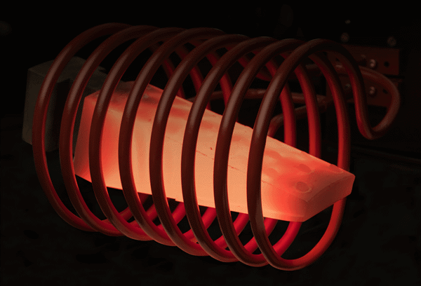
1. Multi-Turn Helical Coil
The most common and the most efficient coil by a long way is the helical (solenoid). As the amount of turns determines the length of the heating pattern, the design is relatively simple.
In this type of coil the workpiece can be stationary in order to supply a defined heating band in “single shot heating.” Alternatively, the workpiece can be moved through the coil to heat a longer part using a highly uniform heating pattern called “scan heating.”
2. Pancake Induction Coil
Pancake induction coils are employed when it is necessary to heat the workpiece from just one side, or when surrounding the part is not possible. Pancake coils can also be utilized to heat a small narrow band in the center of the part. As the flux from only one surface intersects with the workpiece, the pancake coil supplies a huge scope of heating behaviors.
3. Multi-Position Helical Coil
Multi-position coils are frequently utilized to generate more parts in a certain time while enabling the entire heating process. Any amount of positions are possible but usually up to eight positions are practical. Depending on the heating process needed, parts can be heated at the same time, or be indexed in and out of different positions.
4. Split Helical Coil
When it is not possible to access the target heating area using a helical coil, single- or multiple-turn split helical coils are employed.
Conducting Through Split Coils
The faces of the fixed and hinged portions of the coil need good surface-to-surface contact. These are usually faced with silver, or special alloys which are matched to supply good contact. To ensure closure during heating, clamps are utilized. High currents pass through this interface at high frequency, which generally leads to the life of the contact being limited.
Securing Split Coils
To maintain proper coupling distance, split coils usually need a means of finding the part in the coil. Typically, ceramic buttons or pins are secured to the face of the inductor. During heating/quenching they are subject to thermal shock and must be designed for simple replacement.
Quenching Through a Split Coil
Some applications need the split-coil design to have the ability to quench through the face of the inductor. So that excessive heating does not happen in the movable section during the cycle, coolant for the coil chamber of the split inductor is carried by flexible hoses that bypass the hinge.
The quench chamber is fed using a separate hose arrangement. During heating, the face of the quench chamber is nearest to the work, and carries most of the current. It needs to be thick enough to avoid distortion or melting during the heating cycle.
5. Master Work Coils and Inserts
Generally, master coils and inserts are utilized for small batches where a single-turn coil can be employed. Master work coils supply a fast, simple means of altering coil diameters or shapes in order to match a variety of parts.
Usually, master work coils are made up of copper tubing which supply both an electrical connection to the power supply and a water-cooled contact surface for connection to a coil insert. The copper tube is bent into the form of a single-turn coil and soldered to a copper band which is adapted to the slope of the coil insert and is recessed.
6. Butterfly Coils
Butterfly coils are perfect for producing an even heating pattern at the end of a shaft or bar and they have two specially formed pancake coils. So that the current paths are additive, center turns must be wound in the same direction. To create the desired pattern, only these center turns should couple directly with the part. The butterfly “wings” can either be bent up to decouple their fields from the shaft, or can be coupled with the shaft itself.
Solenoid Coil Design Calculations
Coupling Distance
Usually, distance grows with the diameter of the part, normal values being 0.75, 1.25, and 1.75 inches (19, 32 and 44 mm) or billet-stock diameters of around 1.5, 4 and 6 inches (38, 102, and 152 mm), respectively. Uniform heating at high power densities becomes challenging when the length of the coil surpasses 4-8 times its diameter. Single-turn or multi-turn coils that scan the length of the workpiece are usually preferable in these cases.
Coupling Efficiency
Efficiency of coupling between the windings is inversely proportional to the square of distance between them.
Voltage Loss
A maximum of 10 % of the total voltage will be lost in the leads if the inductance of the coil (L2) is approximately ten times the total inductance of the leads (L1 plus L3) or more. Any loss which is lower than this can be considered nominal.
Current
(current in the secondary * # of secondary turns) = (Current in the primary of the transformer * # of primary turns).
Minimum Tubing OD
To allow for water cooling the minimum outer diameter of copper tubing is 0.125 in (0.32 cm).
Rotational Speed
Rotational speeds generating a minimum of 10 revolutions during the heating cycle should be employed for the majority of hardening operations, which are of short duration.

This information has been sourced, reviewed and adapted from materials provided by Ambrell Induction Heating Solutions.
For more information on this source, please visit Ambrell Induction Heating Solutions.