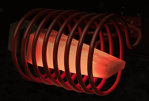
Coupling is the transfer of energy which happens in the space between the heating portion of the coil and the workpiece. Thus, coupling distance is how big a space must be to balance manufacturing requirements and efficiency.
Distance typically increases with the diameter of the part, usual values are 0.75, 1.25, and 1.75 inches (19, 32 and 44 mm) or billet-stock diameters of around 1.5, 4 and 6 inches (38, 102, and 152 mm), respectively. If the length of the coil is over eight times its diameter, uniform heating at high power densities can be challenging. In cases such as these, single-turn or multiple-turn coils that scan the length of the workpiece are often advantageous.
There are three main factors that impact an induction coil’s optimal coupling distance:
1. Type of Frequency and Handling
It is vital to remember that handling and process conditions dictate coupling. Coupling must decrease if the parts are not straight. Coil currents are lower at high frequencies, so coupling must be increased. Coil currents are notably higher at medium and low frequencies, and decreased coupling can supply advantages to mechanical handling.
Usually, coil coupling should be looser where automated systems are employed. The coupling distances which are outlined above are primarily for heat treating applications in which close coupling is needed. In the majority of instances, the distance increases corresponding with the diameter of the part, normal values being 0.75, 1.25, and 1.75 inches (19, 32 and 44 mm) or billet-stock diameters of approximately 1.5, 4 and 6 inches (38, 102, and 152 mm), respectively.
2. Type of Material
Multiple-turn inductors and slow power transfer are used for through-heating of magnetic materials. Coupling distances may be looser in these applications — on the order of 0.25 to 0.38 inch (0.64 to 0.95 cm).
3. Type of Heating
For static surface heating, where the part can be rotated but is not moved through the coil, it is recommended to use a coupling distance of 0.060 inches (0.15 cm) from part to coil. A coupling distance of 0.075 inches (0.19 cm) is typically necessary for progressive heating or scanning, in order to allow for alterations in workpiece straightness. A multiple-turn, fine-pitch coil closely coupled to the workpiece creates an extremely uniform heating pattern.
Similar uniformity can be attained by opening up the coupling between the coil and the part so that the magnetic flux pattern intersecting the heated area is more uniform, yet, this also decreases energy transfer.
Where low heating rates are needed, for example through-heating for forging, this is acceptable. It is best to maintain close coupling when high heating rates are required. To prevent overloading of the generator the pitch of the coil should be opened.
Improving Coupling Efficiency
The efficiency of coupling between the windings is inversely proportional to the square of distance between them. Coil efficiency is the energy transferred to the coil that is delivered to the workpiece. Note that this is not the same as overall system efficiency. Usually, helical coils employed to heat round workpieces have the highest values of coil efficiency and internal coils have the lowest.
It is crucial to remember that the heated part is always in the center of the flux field, with the exception of the pancake and internal coils. The most efficient coils are basically modifications of the standard, round coil, regardless of the part contour.
For example, a conveyor or channel coil can be seen as a rectangular coil whose ends are bent to form “bridges” in order to allow parts to pass through continually. However, the parts always stay where the flux is concentrated “inside” the channels. Areas to be hardened are next to the center of the coil turns, and so are located in the area of heaviest flux.
Coupling over a larger area can be attained through the addition of a liner to the coil turn when a wide heating zone is to be generated on the part, or with a multiple-turn channel inductor more ampere turns can also be produced. Channel-coil liners can also be configured to generate specialized heating patterns where bigger heat densities are needed in particular areas.
This information has been sourced, reviewed and adapted from materials provided by Ambrell Induction Heating Solutions.
For more information on this source, please visit Ambrell Induction Heating Solutions.