Introduction For many years, considerable research efforts have been directed towards exploring the functionalized organic materials for prospective replacement of inorganic optical devices with cost-effective, more functionalized and more reliable optical devices [1]. The increasing need to manipulate optical signals, following in the wake of the introduction of photonics instead of optoelectronics, has stimulated interest in highly functionalized optical devices. Photo-control of molecular orientation of polymer materials is of great interest for highly functionalized holographic optical devices [1]. Several types of organic polymers have been applied to the holographic elements, including photochromic [2-6], photoreactive [7] and UV-curable polymers [8-11]. Among them, many studies of polymers with azobenzene-side groups have been carried out to generate the photoinduced birefringence as well as the holographic optical recording based on cis-trans photoisomerization [2-6, 12, 13]. Additionally, surface relief gratings of the azobenzene-containing polymers are formed by irradiating with interference light [1-6, 12, 13]. Such phase gratings were also fabricated using the photoreactive polymer and/or their composites by means of photoirradiation and simultaneous molecular mobilization. We have reported on reorientation of the mesogenic groups in photocrosslinkable polymer liquid crystals, and their application to optical birefringent films toward high-quality liquid crystal displays [8-11]. For our materials, both reorientation and migration of the mesogenic groups could be expected when the film is exposed to interference light because the photocrosslinked mesogenic groups may change the molecular mobility and the alignment ability of the film. In the present paper, thermally stable holographic grating elements based on both refractive index modulation and surface relief formation of a photocrosslinkable polymer liquid crystal are described. Since the material generates periodic in-plane molecular reorientation on the process of grating formation, polarization holographic gratings, which can diffract the light and convert the polarization states at the same time (polarization convertible grating), are also demonstrated and characterized on the basis of the diffraction theory. Experimental Figure 1 shows the chemical structure of our photocrosslinkable polymer liquid crystal. Our photocrosslinkable polymer liquid crystal contains both mesogenic and photoreactive groups in the polymer side chain. The photocrosslinkalble polymer liquid crystal described in Figure 1 was synthesized according to the literature [8-10] and exhibits a nematic liquid crystalline phase between 116oC and 315oC. | 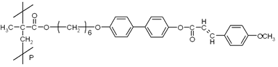
| | Figure 1. Chemical structure of photocrosslinkable polymer liquid crystal. | The thin film of the photocrosslinkable polymer liquid crystal was prepared by a spin-coating method from a methylene chloride solution on to a quartz substrate, resulting in a 300-nm-thick polymer film. The polymer film was amorphous in nature after the spin-coating. According to our previous studies [8-10], the photocrosslinkable polymer liquid crystal used here exhibits thermally stable reorientation of mesogenic side groups by the use of the linearly polarized ultraviolet light and subsequent annealing. Figure 2 illustrates such a thermally stable reorientation of mesogenic groups in the photocrosslinkable polymer liquid crystals. After spin-coating the polymeric material, the mesogenic units are randomly aligned in the film and the polymer film appears transparent as shown schematically in Figure 2(a). When the polymer is irradiated with linearly polarized ultraviolet light, the photoreactive units in the direction of the optical electric field are axis-selectively reacted and other units are not reacted, as shown in Figure 2(b). In this stage in the grating generation processes, the refractive index change is small because the mesogenic units are not regulated. Once the polymer is annealed at elevated temperature, the mesogenic units are regulated in the direction of the photocrosslinked units as shown in Figure 2(c), resulting in large optical anisotropy due to the regulated mesogen. | 
(a) 
(b) 
(c) | | Figure 2. Schematics of the photoregulation of mesogenic molecules in the photocrosslinkable polymer liquid crystal. | Holographic gratings were written using two mutually coherent He-Cd laser beams incident on the sample from the polymer film side. These emit cw 325 nm light, with an intensity of 190 mW/cm2 each. The crossing angle between two writing beams was 9.8 degrees, which forms a grating spacing of about 2 μm. The polarization states of the two coherent writing beams were individually controlled by half and quarter wave plates. The exposure doses were controlled to be 48, 95, 190, and 380 mJ/cm2 by adjusting the irradiation time. After irradiation, the film was annealed at elevated temperature above the melting point (150°C) for 15 min to induce reorientation and molecular migration of the mesogenic groups. The characteristics of the interference light of the two coherent waves are strongly dependent on their polarization states. Figure 3 summarizes the relationship between the polarization states of the two waves and the characteristics of the resultant interference light. The top three cases show the interference light of two coherent waves with parallel polarizations and the bottom three cases show that with orthogonal polarizations. In the case of the parallel polarizations the resultant interference light shows constant polarization and modulated intensity (intensity hologram); while the interference pattern of two coherent waves with orthogonal polarizations has a constant intensity, but a polarization state that is periodically modulated (polarization hologram) as described in the bottom three cases in Figure 3. The diffraction efficiency of the first order diffracted beam from the recorded gratings in the transmission mode was probed with a He-Ne laser at 632.8 nm which normally incidents on the sample film. The diffraction efficiency in the first order was expressed as, η+1=I+1/I0 where I+1 and I0 are the intensity of the first order diffraction beam and incident probe beam, respectively. | 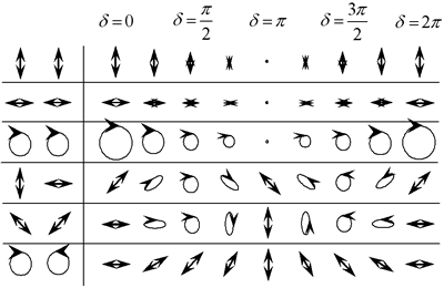
| | Figure 3. Interference light on varying the combination of the polarization states of the two coherent beams. | Results and discussion The diffraction was almost invisible under any writing conditions after irradiation, while the sample was annealed at the liquid crystal temperature of 150°C. The grating was thereupon thermally organized and the diffraction spot appeared. These gratings were quite stable in ambient atmosphere and their optical properties were reproducible. Figure 4 shows atomic force microscope (AFM) investigation of the surface structure of the recorded gratings on varying the polarization states of the two recording beams. The AFM investigation reveals that surface relief gratings appear in the case of the intensity holograms, as shown in Figures 4(a) and 4(b), while they are almost invisible for the polarization holograms [see Figures 4(c) and 4(d)]. Figure 5 summarizes the mechanism for generating the surface relief gratings. In the case of the intensity holographic recording, the intensity of the interference light is modulated in space as summarized in Figure 3, therefore there are spatial distributions of photoreactive compounds in the polymer films. Due to this density distribution, during the annealing processes, the polymeric materials migrate from the high density region to the low density region as shown in Figure 5(a). In contrast, in the case of the polarization holographic recording, the intensity of the interference light is not modulated and only the polarization state is modulated in space. In such cases, the density of the photoreactive compounds is homogeneous in the polymer film and the polymer cannot migrate, only the reorientation of the mesogenic molecules can occur during annealing, as schematically described in Figure 5(b). | 
| | Figure 4. Typical AFM three-dimensional view of (a), (b) intensity holographic recorded gratings and (c), (d) polarization holographic recorded gratings on the photocrosslinkable polymer liquid crystal. | | 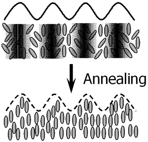
(a) 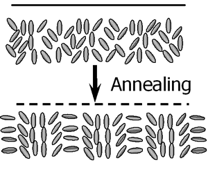
(b) | | Figure 5. Schematics of the surface relief grating generation for (a) intensity holographic recordings and (b) intensity holographic recordings. | The diffraction efficiency was measured as a function of the light polarization azimuth α, which was adjusted by rotating the polarization direction of the linearly-polarized He-Ne laser beam using a half-wave plate. Figure 6 plots the diffraction efficiency of the recorded gratings with various exposure doses as a function of the azimuth α. As shown in Figure 6, the diffraction efficiency of the intensity holographic gratings is greatly dependent on the polarization azimuth of the He-Ne probe beam, while that of the polarization holographic grating is hardly dependent on the polarization azimuth. Figure 6(a) shows the diffraction efficiencies of the gratings recorded with two coherent beams with parallel s-polarizations. In this case, the mechanism of induced phase grating formation is linked with both reorientation of the mesogenic director and the polymer migration. One has to notice that the sign of the induced birefringence is reversed at an exposure energy between 95 and 190 mJ/cm2. We reported that thermally enhanced photoinduced reorientation of the mesogenic groups in the photocrosslinkable polymer liquid crystals was generated based on the axis-selective photoreaction and thermal motion of the mesogenic groups in the photocrosslinkable polymer liquid crystals when the polymer was irradiated with linearly polarized ultraviolet light, followed by annealing. According to our previous studies, the direction of thermally enhanced molecular reorientation is dependent on the degree of the photoreaction and distribution of the photoproducts. Thermal amplification of the photoinduced negative optical anisotropy was generated when the degree of the photoreaction was less than 10%. In contrast, reversion of the reorientation direction parallel to the optical electric field was induced when the degree of the photoreaction was between 15 and 20%. Therefore, the difference in the azimuth angle dependence of the diffraction efficiency among the exposure doses should be related to the birefringence and reorientation direction of mesogenic groups in the exposure region. To understand the grating formation, an intuitive method for estimating the diffraction efficiency was carried out. At present, we presume that the two writing beams with parallel polarization directions generate linear birefringence and change the ratio of the characteristics ellipsoid without changing the directions of the principle axes. Under this condition, the refractive index varies with the azimuth angle  , and it is expressed as the following equation: , and it is expressed as the following equation: 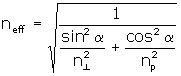 (1) (1)
where n⊥ and np are the principle refractive indices in the perpendicular and parallel direction of the electric field vector of the writing beams. In addition, the gratings due to linear anisotropy and surface relief appear at the same time. The total effective phase difference of the recorded hologram can be obtained as: 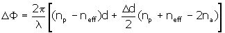 (2) (2)
where np and na are the refractive index before writing and that of air, respectively, d is the initial film thickness, and Dd is the surface-modulation depth. For a linearly polarized probe beam, the first-order diffraction efficiency is:  (3) (3)
where J12(DF) is the first order Bessel function of the first kind in DF. As shown in Figure 6(a), the experimental results are well-explained by using Eq. (3) and the induced birefringence on varying the exposure energy of 48, 95, 190, and 380 mJ/cm2 was estimated to be -0.057, -0.055, 0.029, and 0.052, respectively. | 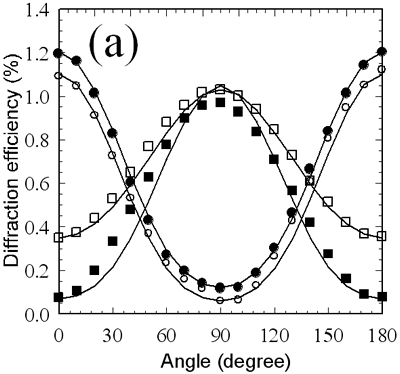
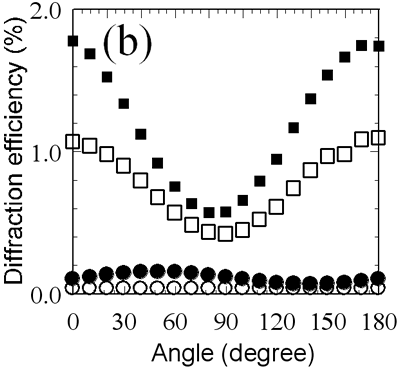
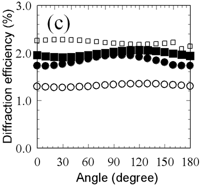
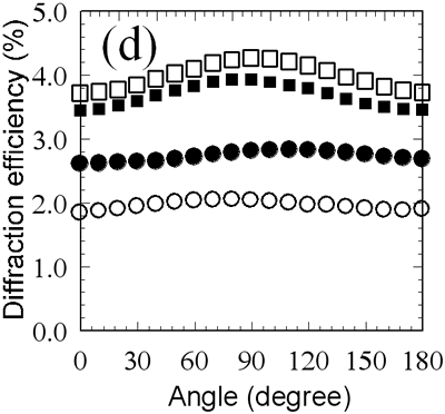
| | Figure 6. Diffraction efficiency of (a) parallel linear, (b) parallel circular, (c) orthogonal linear, and (d) orthogonal circular phase gratings as a function of incident light polarization azimuth. The exposure doses are 48 (open circles), 95 (closed circles), 180 (open squares) and 380 (closed squares) mJ/cm2. Four solid lines in (a) represent theoretically fitted curves. | The parallel circular mode comprised two circular beams polarized in the same circular direction, and this mode featured intensity modulation with constant circular polarization, as shown in Figure 3. Since the polarization of the interference light is always circular, the axis-selective reaction in the photocrosslinkable polymer should not occur for such a writing mode, and an anisotropic grating is not expected to be formed under such experimental conditions. However, gratings showed strong optical anisotropy as the surface relief gratings were growing in the polymer films, as shown in Figure 6(b). These results and the above-mentioned consideration suggest that polymer migration during the annealing process induces reorientation of the mesogenic molecules, although axis-selective photoreaction does not occur. Figures 6(c) and 6(d) plot the diffraction efficiencies versus azimuth angles of the probe beam when the polarization gratings were written with the two coherent waves with orthogonal polarizations. Irradiating films with orthogonal linear and orthogonal circular modes gave different results. Surface relief was barely observed in the polarization gratings formed in the orthogonal polarization modes, as shown in Figures 4(c) and 4(d). Therefore, these phase gratings correspond to the pure polarization gratings generated by the reorientation of the mesogenic groups of the photocrosslinkable polymer liquid crystals according to the polarization information of the interference beams illustrated in Figure 3. A theoretical framework taking into account the properties of the diffraction beams from the pure polarization gratings is needed for quantification of the results. In the case of the orthogonal linear mode, the optic axis of the induced birefringence is always slanted 45° against the x-y coordinates (laboratory axes). Therefore, light propagation in the polarization gratings can be described from the linear combination of extraordinary and ordinary waves. This can be done by the coordinate transformation: 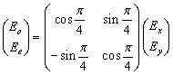 (4) (4)
where the x and y axes are fixed laboratory axes, and the o and e axes are fixed in the medium. The two components, o and e, are normal modes of the polarization gratings and will propagate with their own phase velocities and polarizations. Because of the difference in phase velocity, one component is relative to the other. This retardation changes the polarization state of emerging and diffracted beams. The electric fields of the emerging beam in the medium o-e coordinate system is given by: 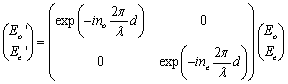 , (5) , (5)
where d is the thickness of the polarization grating and λ is the wavelength of the probe beam. Assuming that the refractive index change is proportional to the light electric field, the refractive indices, ne and no, can be written as: | 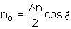
| (6) | | 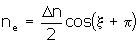
| (7) | where ∆n is the induced birefringence. The electric field of the emerging beam in the x-y coordinate is given by transforming back from the o-e coordinate system: 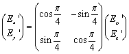 . (8) . (8)
On the basis of Fraunhofer’s diffraction phenomenon, the electric fields of the diffraction beams are given by: | 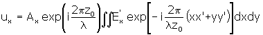
| (9) | | 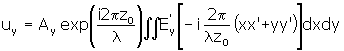
| (10) | where Ax and Ay are determined from the polarization condition of the probe beam, and zo is the distance between the sample and a screen. The polarization condition of the diffraction beam is expressed as the elliptic function: 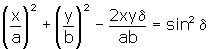 (11) (11)
where a=Re(ux) , b=Re(uy), and 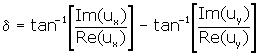 (12) (12)
According to the above-mentioned theory we can calculate the diffraction properties of the polarization hologram. For the orthogonal linear polarization gratings, the  first-order diffraction beams were linearly p-polarized when the reading beam was linearly s-polarized, while first-order diffraction beams were linearly p-polarized when the reading beam was linearly s-polarized, while  first-order diffraction beams were left-hand side circularly polarized when the reading beam was right-hand side circularly polarized. For the orthogonal circular polarization gratings, the + first-order diffraction beam was left-hand circularly polarized and the – first-order diffraction beam was right-hand circularly polarized when the reading beam was linearly s-polarized. first-order diffraction beams were left-hand side circularly polarized when the reading beam was right-hand side circularly polarized. For the orthogonal circular polarization gratings, the + first-order diffraction beam was left-hand circularly polarized and the – first-order diffraction beam was right-hand circularly polarized when the reading beam was linearly s-polarized. When the reading beam was right-hand side circularly polarized, the + first-order diffraction beam was left-hand side circularly polarized, while the – first-order diffraction was invisible. These theoretical expectations of the polarization conversion properties were consistent with the experimentally observed results as shown in Figures 7 and 8. | 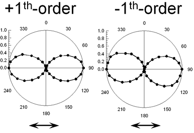
(a) 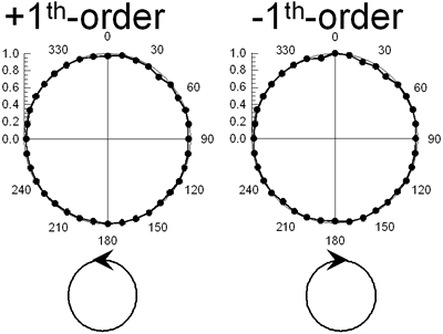
(b) | | Figure 7. Polarization analysis of the beams diffracted from (a) orthogonal linear and (b) orthogonal circular polarization gratings. The reading beam is p-polarized. | | 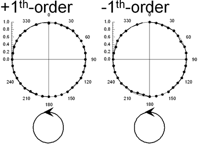
(a) 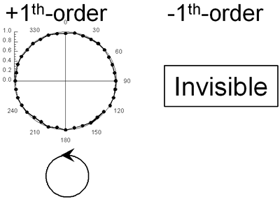
(b) | | Figure 8. Polarization analysis of the beams diffracted from (a) orthogonal linear and (b) orthogonal circular polarization gratings. The reading beam is right-hand side circularly polarized. | Conclusions Highly stable and functionalized polarization holographic devices using photocrosslinkable polymer liquid crystals have been demonstrated. The grating is almost invisible immediately after irradiation with ultraviolet interference light, but the grating appears after annealing the film in the liquid crystalline temperature range of film. The diffraction measurement and AFM observation revealed that the intensity holographic gratings involve both linear birefringence and surface relief, while the pure polarization gratings without surface topological relief were formed for the polarization holographic recordings. We anticipate that these unique phenomena of the material and phase grating can be applicable to various kinds of optical devices. Acknowledgements This work was partially supported by Iketani Science and Technology Foundation. The authors also wish to express their gratitude to the Japanese government for partially supporting this work through the 21st Century Center of Excellency (COE) Program of the Ministry of Education, Culture, Sports, Science and Technology. References 1. “Polymers As Electronical And Photooptical Active Media, (Ed. V. P. Shivaev), Springer, Berlin, (1996). 2. T. Todorov, L. Nikolova And N. Tomova, “Polarization Holography. 1: A New High-Efficiency Organic Material With Reversible Photoinduced Birefringence”, Appl. Opt., 23, (1984) 4309-4312. 3. H. Ono, N. Kowatari And N. Kawatsuki, “Study On Dynamics Of Laser-Induced Birefringence In Azo Dye Doped Polymer Films”, Opt. Mater., 15 (2000) 33-39. 4. Y. Shi, W. H. Steier, L. Yu, M. Chen And L. R. Dalton, “Large Stable Photoinduced Refractive Index Change In A Nonlinear Optical Polyester Polymer With Disperse Red Side Groups”, Appl. Phys. Lett., 58 (1991) 1131-1133. 5. P. Rochon, J. Gosselin, A. Natansohn And S. Xie, “Optically Induced And Erased Birefringence And Dichroism In Azoaromatic Polymers”, Appl. Phys. Lett., 60 (1992) 4-6. 6. Y. Wu, Y. Demachi, O. Tsutsumi, A. Kanazawa, T. Shiono And T. Ikeda, “Photoinduced Alignment Of Polymer Liquid Crystals Containing Azobenzene Moieties In The Side Chain. 2. Effect Of Spacer Length Of The Azobenzene Unit On Alignment Behavior”, Macromolecules, 31 (1998) 1104-1108. 7. M. Schadt, K. Schmitt, V. Kozinkov And C. Chigrinov, “Surface-Induced Parallel Alignment Of Liquid Crystals By Linearly Polymerized Photopolymers”, Jpn. J. Appl. Phys., Part 1, 31 (1992) 2155-2164. 8. N. Kawatsuki, H. Takatsuka, T. Yamamoto And O. Sangen, “Optical Anisotropy Of Photoreacted Side-Chain Liquid-Crystalline Polymer Induced By Linearly Polarized Uv Light”, J. Polym. Sci., Part A: Polym. Chem., 36 (1998) 1521-1526. 9. N. Kawatsuki, T. Yamamoto And H. Ono, “Photoinduced Alignment Control Of Photoreactive Side-Chain Polymer Liquid Crystal By Linearly Polarized Uv Light”, Appl. Phys. Lett., 74 (1999) 935-937. 10. N. Kawatsuki, K. Goto, T. Kawakami And T. Yamamoto, “Reversion Of Alignment Direction In The Thermally Enhanced Photoorientation Of Photo-Cross-Linkable Polymer Liquid Crystal Films” Macromolecules, 35 (2002) 706-713. 11. H. Ono, A. Emoto, F. Takahashi, N. Kawatsuki And T. Hasegawa, “Highly Stable Polarization Gratings In Photocrosslinkable Polymer Liquid Crystals”, J. Appl. Phys., 94 (2003) 1298-1303. 12. L. Nikolova, T. Todorov, M. Ivanov, F. Andruzzi, S. Hvilsted And P. S. Ramanujam, “Polarization Holographic Gratings In Side-Chain Azobenzene Polyesters With Linear And Circular Photoanisotropy”, Appl. Opt., 35 (1996) 3835-3840. 13. F. Ciuchi, A. Mazzulla And G. Cipparrone, “Permanent Polarization Gratings In Elastomer Azo-Dye Systems: Comparison Of Layered And Mixed Samples”, J. Opt. Soc. Am., B 19 (2002) 2531-2537. Contact Details |