Heat exchangers transport thermal energy between two or more media, which might be fluid–fluid or fluid–gas systems. The heat transmission process is carefully examined while designing heat exchangers, which may include many types of heat transfer.
Heat exchangers are widely used in a variety of areas of the economy in which controlled heating or cooling of flow streams, managed evaporation, or monitored condensation is required, such as ventilation and air conditioning systems (HVAC), energy production industries, chemical processing, and manufacturing facilities.
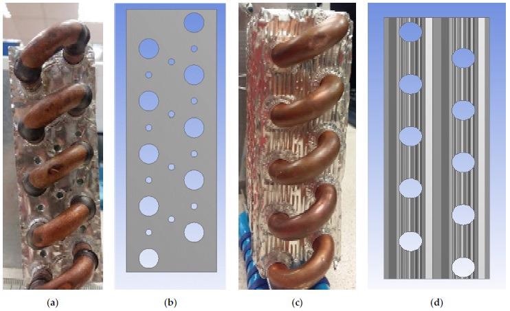
(a) Picture of perforated plain fin type heat exchanger, (b) perforated holes’ arrangement, (c) louvred fins heat exchanger, (d) louvred fin shape. Image Credit: Atwieb, M., et al., Energies
Analysis and Design of Heat Exchangers
Expertise and adherence to these throughout the design phase are critical to ensuring appropriate and efficient functioning. Heat exchanger analysis and design methods have improved significantly over the years as a result of intensive study in this field, and there is presently a strong emphasis on optimizing such systems.
The primary goal of this research is to improve the heat transfer rate and minimize pumping expenses, as well as expenditures related to the size and weight of the heat exchanger. In general, optimization techniques may be divided into two types: active and passive. An external force is employed to drive heat transfer performance in the first category.
![Variation of (Qavg [W]) against Va for various heat exchangers; (a) for water flow rate 0.12 m3/h, (b) for water flow rate 0.18 m3/h, (c) for water flow rate 0.24 m3/h, (d) for water flow rate 0.3 m3/h and (e) for water flow rate 0.36 m3/h.](https://www.azom.com/images/news/ImageForNews_57856_1641558339051578.jpg)
Variation of (Qavg [W]) against Va for various heat exchangers; (a) for water flow rate 0.12 m3/h, (b) for water flow rate 0.18 m3/h, (c) for water flow rate 0.24 m3/h, (d) for water flow rate 0.3 m3/h and (e) for water flow rate 0.36 m3/h. Image Credit: Atwieb, M., et al., Energies
Previous Approach to Detect Efficiency
An experimental approach was created for determining the efficiency of different heat transfer technologies. The obtained convection coefficients were used to quantify the process performance.
The influence of fin (thickness, spacing) and tube (amount of rows) factors on typical flow and heat transfer properties were also investigated. Researchers discovered that fin thickness and spacing had only a small impact on flow and heat transfer properties.
It was built a prototype model to test heat transfer coefficients in the vapour formation and condensation processes using heat exchanger tubes They expanded the usage of the underlying concept to a variety of convective heat transfer scenarios, noting that design engineers dealing with thermal difficulties would benefit from it.
Limitations
Most studies have concentrated on the simple arrangement of perforations in plain fins, with little information available on complicated perforations in plain fins. There is very little information available about louvered fins.
Perforations are used to improve passive heat transmission in heat exchangers. The influence of fin perforations on locally and globally performance metrics is an important and continuing field of study that deserves more investigation.
Furthermore, the bulk of design equations provided have a very narrow range and do not consider various geometric characteristics such as fin pitch, spacing, and the existence of perforations.
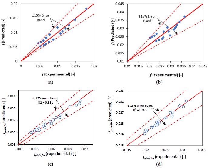
Comparisons of predicted (by Equations (9) and (10)) and experimental values of (a) Colburn j-factor and (b) Fanning f-factor (c) plain fin Colburn factor (d) plain fin Fanning factor. Image Credit: Atwieb, M., et al., Energies
New Research Process
The new findings evaluate the steady-state heat transfer and thermal performance of a variety of fin design (plain, louvred, and perforated fin) heat exchangers experimentally. New mechanical estimation techniques for the Colburn factor and the Fanning friction factor as a function of Reynolds number and heat exchanger shape were created and their estimated error margins were investigated using experimental results. These equations are expected to aid in the construction and optimization of these heat exchanger setups.
Result Shows Louvred Fin is Among the Best
Geometric layouts for multi-tube multi-fin heat exchangers were created that are new. The configurations were created in order to undertake a rigorous experimental analysis using three different heat exchanger geometric shapes: plain, perforated plain, and louvred fin heat exchangers. During the trials and examination of the pressure drop and heat transfer data, several significant findings were obtained.
The louvred fins generated the maximum heat transfer rate for all intake air and water flow rates, and so velocities. This was ascribed to an increase in the available surface area for heat transmission. When compared to the other two designs, it also generated the biggest pressure losses.
Furthermore, although the novel perforated design created a slightly larger pressure drop than the plain fin design owing to the vortices formed by the perforations, it demonstrated improved heat transfer characteristics compared to the plain and louvred fin models. At quite a low water flow rate, this augmentation is rather high.
Advantage of this Experiment
The experimental data were then utilized to develop a set of innovative empirical equations for design optimization that can be used to anticipate the heat transfer and pressure drop features of heat exchangers indicated by the Colburn and Fanning factors.
The equations were created as variables of the geometrical characteristics of the heat exchangers, and we demonstrated that their performance is well within acceptable 15 percent error margins in respect to the experimental results.
Reference
Atwieb, M., et al. (2022). Heat Transfer Enhancement by Perforated and Louvred Fin Heat Exchangers. Energies 2022, 15(2), 400; Published: 6 January 2022 https://www.mdpi.com/1996-1073/15/2/400
Disclaimer: The views expressed here are those of the author expressed in their private capacity and do not necessarily represent the views of AZoM.com Limited T/A AZoNetwork the owner and operator of this website. This disclaimer forms part of the Terms and conditions of use of this website.