The next generation of large scale telescopes will need durable mirrors that are highly reflective, uniform and have substrate diameters in excess of 8 meters.
Traditionally, evaporative coatings have required a broad source coverage and high deposition rate to effectively evaporate a reflective coating. Moreover, extreme care needs to be taken to prevent oblique angle evaporation, which can result in the growth of columnar structures and reduce reflectivity.
Sputtering Techniques
Sputtering is a unique technique that provides a suitable solution for both single and multilayer reflective coatings across large substrates. Long throw sputtering is a widely used technique for semiconductor processes, and provides enhanced density and coating adhesion when compared to evaporated coatings.
This technique creates uniform coatings across the entire mirror curvature and requires minimal masking. However, long throw sputtering of aluminum has not yet been effectively applied to large scale telescope applications. Short-throw sputtering is another technique that requires increased facility capabilities and sophisticated masking to compensate for mirror curvature.
This article demonstrates a range of experiments to assess the impact of long-throw sputtering parameters on mirror reflectivity compared to a traditional front surface aluminum mirror.
Experimental Procedure
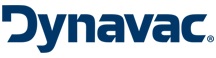
A standard Dynavac 36” optical coating system was used to perform all experiments; two different experimental configurations were used. The first experimental setup uses two 2” diameter Materials Science Polaris Gen II magnetron sputtering sources.
The first magnetron (Magnetron 1) is placed vertically to sputter material on horizontal glass test slides affixed 30cm directly above the magnetron. The second magnetron (Magnetron 2) is placed in the same horizontal plane, 40cm apart from Magnetron 1.
It is then tilted towards the glass slide to increase rate at a ~53° incidence angle. In order to control the flow of argon gas to the magnetrons, both magnetrons utilize MKS 1179A mass flow controllers and 1100 aluminum sputtering targets.
Figure 1 shows a basic diagram of the chamber setup.
.jpg)
Figure 1. Side schematic of experimental setup 1. Two magnetrons are mounted in a plane h=30cm below a horizontal glass slide and QCM sensor. The second magnetron, labeled ”Mag2”, is a distance d=40cm from the first magnetron labeled”Mag1”.
The magnetrons are powered by an Advanced Energy 5kW MDX power supply; the deposition process is controlled through Labview based control software from Dynavac. The deposition rate is determined by means of an Inficon 6 MHz Front Load Dual Quartz Crystal Monitor (QCM) positioned next to the glass slide in the same horizontal plane. An Inficon IC/5 Thin Film Deposition Controller is used to control the QCM.
The system is then pumped through the Brooks Cryogenics OB-400 cryopump to provide about 11m3/sec of net water vapor pumping to the system. In addition, a liquid nitrogen cold plate measuring 180mm diameter is installed within the chamber for additional 8m3/sec of water vapor cryopumping. All vacuum gauging is determined by means of an Instrutech IGM402 Hornet Hot Cathode Bayard-Alper ionization gauge equipped with CVG101 Worker Bee convection enhanced Pirani gauge.
The second experimental setup used a single 2” diameter Materials Science Polaris Gen II magnetron sputtering source, which is horizontally positioned in the system to provide a d=72.4cm throw distance.
The magnetron is then integrated with a 99.999% pure aluminum target. Next, glass slides are placed vertically in the chamber on a same-sized mounting bracket utilizing Kapton tape. The mounting bracket is set on a ThorLabs MSRP01/M Mini-Series rotation platform to accurately control the incident angle relative to the fixed sputtering cathode position.
Figure 2 shows a diagram of the experimental setup.
.jpg)
Figure 2. Overhead schematic of Experimental setup 2. A single magnetron is mounted horizontally in the chamber, d=72.4cm from a test slide.
.jpg)
Figure 3. Two example RGA scans, with (orange) and without (blue) the LN2 cold plate operating. The most prominent peak in both scans, H2O+ ions at 18 amu, decreases by a factor of two when the cold plate is below -140 ºC.
In order to provide background gas characterization, an Ametek Dycor Dymaxion 50 amu Residual Gas Analyzer (RGA) is mounted on the chamber. Figure 3 shows two example scans.
Results and Discussions
A Tencor Alphastep 200 automatic step profiler is used to measure the deposition thickness on all the test slides. All test slides are then subjected to an adhesion “tape-test”, which was passed by all the slides.
Sputtered reflectivity measurements are carried out with the help of a Shimadzu UV-2401PC UV-Vis Recording Spectrophotometer with a Harrick Near-Normal Incidence Specular Reflection Attachment over wavelengths from 400 to 900nm.
Next, absolute reflectance measurement of the standard aluminum front surface mirror was performed on an Agilent Cary 5000 spectrophotometer and these measurements were further corrected at 635nm using a Thorlabs CPS180 1mW diode laser quantified with a Thorlabs DET36A biased Si photo-detector to 89.8 % average absolute reflectance.
Leveraging the first experimental setup, initial tests tried to establish whether there was a decrease in reflectivity when long-throw sputtering at high incidence angles. The results are illustrated in Figure 4.
.jpg)
Figure 4. Comparison of the reflectivity of coatings produced by Magnetron 1 at 600W and Magnetron 2 at 600W. The longer throw distance decreases the deposition rate by a factor 5 (greater than ar-2 assumption would suggest).
The first magnetron was operated at a steady power of 600W with 35 sccm of argon flowing to the cathode. During deposition, the chamber pressure was 2×10⁻⁴ Torr, and during a 100nm deposition an average deposition rate of 2.08A/sec was determined on the crystal monitor.
The reflectivity is plotted as the blue curve in Figure 4. Likewise, the second magnetron 2 was operated with the same parameters with the test slide reflectivity shown as the orange curve. Over 1% decrease in relative reflectivity was measured.
However, because of the increased source to substrate distance, the deposition rate reduced to 0.39A/sec. As a result, the deposition time extended from 8 to 42 minutes for a 100nm deposition.
Next, the first magnetron was operated at a lower constant power of 100W to reproduce a similar lower deposition rate. Similar experiments were performed at a higher sputtering pressure (7 × 10⁻⁴ Torr, 65 sccm argon) with corresponding results.
The decrease in reflectivity together with decreasing rate implies that particles other than aluminum are blending into the reflective coating. In Figure 3, the blue RGA scan suggests that water vapor would be the driving concern, and that the chamber would considerably benefit from extra water vapor pumping.
Experimental test setup 2 helped in studying the change in reflectivity with angle and ensured a constant incident rate of aluminum. As the incident angle increases, the reflectivity decreases. While with increasing incident angle, the thickness of deposited aluminum on the test slides also decreases.
Figure 5 shows a plot of the measured thickness versus incident angle. Additional testing is needed to estimate the precise relationship between reflectivity and incident angle independent of thickness and deposition rate.
.jpg)
Figure 5. Deposition thickness as a function of incident angle. Deposition for each test slide stopped when the quartz crystal monitor thickness was measured to be 1000A.
The results of the experimental setup 1 indicate that incidence angle may not be the driving concern when coating large scale telescope mirrors. As a result, a set of coatings were created using experimental setup 2.
By averaging the reflectivity of each test slide across the quantified wavelength range from 400 to 900nm, the effect of additional water vapor pumping in the system can be more easily observed. These averaged reflectivities are plotted in Figure 6 as a virtue of delay time.
.jpg)
Figure 6. Reflectivity of annular joint samples as a function of delay between first and second layers. The first layer is stopped at 80A and the second layer is 20A. Additional water vapor pumping enhances the reflectivity of both the base coating and the annular joint.
The reflectivity of the zero delay mirror and the degradation of the 80% annular joint is clearly enhanced with additional water vapor pumping. These results provide a viable reason for including large quantities of water vapor pumping in aluminum long and short throw sputtering chambers to prevent annular joint reflectivity problems.
Conclusion
Experimental results indicate that water vapor control is the leading factor in creating durable and highly reflective aluminum mirror coatings, and also suggest that long throw sputtering in a low water partial pressure environment can be very effective.
About Dynavac - High Vacuum Thin Film Deposition
For over 30 years Dynavac has been designing and manufacturing Thin Film Deposition System for evaporation, sputtering and PECVD applications. System configurations are offered for batch, inline and large-area deposition. We are distinguished by our “Concept to Commission” capabilities, working with customers from the earliest exploration of an idea through full-service commissioning.
This information has been sourced, reviewed and adapted from work by A. J. Bourque and J. H. Gurian of Dynavac.
For more information on this source, please visit Dynavac - High Vacuum Thin Film Deposition.