| The importance of seal design is widely understood in the process, aerospace, automotive and other industries. Often, when a seal fails, a considerable amount of money is involved in replacing it and in the most extreme cases process equipment worth tens of millions may have to be shut down until the seal is replaced. In many applications, mechanical seals provide a safeguard against hazardous materials escaping into the environment. Another important consideration in seal design is energy consumption since the frictional properties of the seal often have a big impact on the amount of power consumed by the machinery on which it is used. Classes of Seals There are four basic classes of seals which cover the vast majority of applications: • Traditional contact seal that is lubricated by the process fluid flowing through the equipment. • Seals that are cooled and lubricated by the fluid separated from the process. • Seals that run dry with the lubricant derived from the seal material. • Seals lubricated by gas which can either come from the process or be introduced externally. Materials Selection For every seal application there is an optimal pair of rubbing materials that provides the longest life and the lowest operating cost. This rubbing pair must be selected from scores of seal nose materials and an equally large number of mating face materials. The right choice of materials for the mating pair can easily increase seal life fivefold in those applications where wear is the controlling factor. Surface Finish Seal rings are usually received from the supplier in machined form and face preparation operations are then performed to achieve the required finish. A very flat and smooth finish is normally required to prevent leakage. Depending on the seal type and application, materials such as carbon and silicon carbide are commonly used seal materials (see figure 1). The mechanical properties of some seal face materials are given in table 1. | 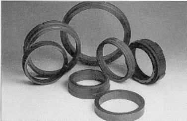
| | Figure 1. Assortment of carbon/graphite and silicon carbide seal rings | Table 1. Mechanical seal face material properties | | | Resin impreg carbon P-658RC | 1.8 | 95 | 235 | 9 | 260 | | Antimony impreg carbon P-7465 | 2.3 | 95 | 275 | 16 | 375 | | Salt impreg carbon P-4229 | 1.9 | 100 | 290 | 16 | 480 | | Siliconised graphite PE-8148 | 2.0 | (2000) | 85 | 50 | 260 | | Reaction bonded silicon carbide PR-9242 | 3.1 | (2400) | 2750 | 145 | 1370 | | Silicon carbide/graphite composite PG-9723 | 2.8 | Na | 550 | 150 | 550 | | Sintered silicon carbide Hexoloy SA | 3.1 | (2800) | 3900 | 125 | 1650 | | Tungsten carbide 6% Ni bonded | 15.0 | (1800) | 4000 | 100 | 900 | | Alumina 99.5% | 3.9 | (1200) | 2600 | 35 | 1500 | | | | | | | | Spiral Technology A recent development is spiral technology. This technique provides a dry running, non-contacting double seal cartridge that ensures zero emission of process fluid to plant atmosphere. Clean dry buffer gas, normally plant nitrogen, is injected into the seal chamber at just 1 to 2 bar above the process pressure. At the inboard seal, the spiral groove pattern on the mating ring/seat pumps the gas towards the ungrooved portion of the face. This compressed gas cushion serves as a sealing dam to block escape of the fluid being sealed. The material used in the seal is still critical because there is contact when the unit starts and shuts down. Carbon is nearly always used because of its self-lubricating properties. Summary Seal manufacturers are meeting the demands for longer life, zero emissions and low power consumption. The wide ranges of seal materials available today provide a wealth of opportunity for optimising seal performance. Careful attention to material selection will pay dividends in reduced maintenance cost and downtime. |