Introduction Pulsed electric current sintering (PECS), which is called commercially spark plasma sintering (SPS) or plasma activation sintering (PAS), is used as a rapid sintering method to densify various materials[1-6]. A powder sample is pressed in an electroconductive die, and a pulsed electric current is applied to both sample and die or only die to generate Joule heating. In the case of PAS, pulsed electric current is applied at only the initial stage of the process. On the other hand, pulsed current is applied during the all stages of SPS. In comparison with conventional resistance-sintering processes, low voltage ranging from 2 to 5 V and high current from 500 to 10000 A are applied in PECS methods [7]. PECS is also a promising method to produce high-performance porous materials [1-4]. Since homogeneous microstructure is one of the important properties of porous materials, there are some reports on microstructure of porous metals made of coarse powder prepared by using PECS. Kouno et al. [8] reported that porous Ti made of the powder ranging from 63 to 106 μm in particle size had homogeneous microstructure. Nanko et al. [9] reported that the microstructure of porous cast-iron made of 200 μm powder was homogeneous. There are few reports on microstructure of porous metals made of fine powder with several microns by using PECS. Ozaki et al. [10] reported that density in the central part of sintered Al powder with less than 10 μm was significantly lower than near the surface in the initial stage of PECS process. Nanko et al. [11] reported that the central part of partially sintered Ni-20Cr with 5 μm in particle size by using PECS was significantly denser than the part near the surface in spite of homogeneous microstructure in the case of 70 μm powder made of Ni-20Cr alloy. They also report inhomogeneous porous structure in the partially-sintered metals when their fine powders were sintered by PECS method [12]. Homogeneity in density of the partially–sintered metallic bodies by using PECS is discussed in this paper. In order to obtain homogeneous microstructure, effects of geometry of graphite die is investigated. Fine Ni-20Cr powder with particle size of 5 μm and coarse powder with 70 μm in particle size were used in order to discuss effects of powder size. Experimental Procedure Commercial Ni-20Cr powders with 5 μm and 70 μm in average particle size (Sanyo Special Steel Co. Ltd.) were used. The compositions of the powder are shown in Table 1. The particles of the powders are shown in Figure 1. Table 1. Chemical composition of Ni-20Cr powders used in this study. | | | fine (5 μm) | 0.002 | 1.26 | <0.02 | <0.001 | 0.002 | Bal | 19.93 | 0.15 | | coarse (70 μm) | 0.077 | 1.41 | 0.35 | - | - | Bal | 19.85 | 0.86 | 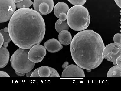
(a) 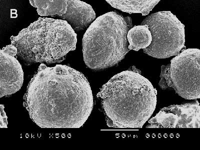
(b) Figure 1. Powder particle of Ni-20Cr. a) 5 µm particle size and b) 70 µm particle size Spherical particles of the both powders are observed. The sintering experiments were performed by using Dr. Sinter Model SPS-1050 (Sumitomo Coal Mining Co. Ltd.). Table 2 shows graphite die types used in the present work. Table 2. Specifications of the graphite die | | | SR | φ 30 | φ 15.4 | 30 | | LD | φ 50 | φ 15.4 | 30 | Two different graphite dies were used to investigate influences to sample homogeneity; SR (PECS -supplier recommended, OD:φ30(IDφ15)× H30), LD (larger outer diameter than SR, φ50(φ15)×30) The punches with φ15×20 were used for SR and LD dies. Figure 2 illustrates the location of sample and thermocouple for the PECS process. High purity graphite sheets were inserted not only between graphite punches and the sample, but also between sample and die. Temperature control during the PECS process was carried out by using a K-type thermocouple located in the die inside with 1mm from the sample/die interface. The temperature measured by using this thermocouple was nominated as die temperature. Figure 3 shows a typical PECS schedule (700ºC at die temperature for 5 min) in the present study. Sintering was carried out at 650 to 800ºC of die temperature for 5 min under a uni-axial pressure of 13 MPa. In order to achieve homogeneous heating of sample, die temperature was increased to the temperature which was 50ºC lower than sintering temperature for 8 min and then reached to sintering temperature for 2 min. After the sintering process, the applied pressure was rapidly removed, and the sample was cooled to the room temperature in vacuum. For each sintering condition, 3 or 5 samples were prepared. Figure 4 shows a schematic illustration of thermocouple set-up in sample surface temperature measurements. In each die type, temperature at the interface between sample and punch was measured by inserting a K-type thermocouple at the upper punch, in advance of the sintering experiments. The temperature is called as sample surface temperature, Ts, as a typical temperature of sample. 
Figure 2. Schematic illustration of the graphite die set-up with thermocouple for temperature control 
Figure 3. Temperature and pressure profile on PECS 
Figure 4. Schematic illustration of a die for measuring sample surface temperature Bulk density of porous Ni-20Cr was measured by the liquid replacement method using toluene. Macroscopic homogeneity of porous bodies was evaluated by observing the cross-section prepared by polishing with 4 μm-diamond abrasive grains. Microstructure of the sintered body was observed by using a scanning electron microscope (SEM). Results Sample Surface Temperatures Figure 5 shows the relationship between sample surface temperature and die temperature. The value of Ts in each die type is higher than die temperature, Tdie. The differences of Ts and Tdie are 50°C in SR die, and 10°C in LD die for fine powder case. PECS of the coarse powder with SR die shows approximately 35°C higher Ts than Tdie. PECS of the fine powder with SR die shows approximately 5°C higher Ts than that of the coarse powder. 
Figure 5. Relationship between die temperature and sample surface temperature Relative Density of the Sample Figure 6 shows relative density as a function of Ts. The values of relative density plotted in Figure 6 are average ones of 3 or 5 samples. The error bars show maximum and minimum values. Density of as-pressed powder compact, i.e., sample before PECS, was 0.59 in each powder. Significant difference in average density is not observed in the die types. A good reproducibility in densification was obtained in each experimental condition. With increasing temperature, densification rate of the fine powder is higher than the coarse powder. Temperature dependence on densification (slope in Figure 6) of the fine powder is larger than that of the coarse powder. 
Figure 6. Relationship between sample surface temperature and relative density Observation of Cross-Section of Sample Figure 7 shows the typical cross-sections of the samples made with the fine powder at 700°C of die temperature with different die geometry. Cross-section of sample produced with LD is more homogeneous than that by using SR die. The sample sintered by using SR die has a microstructure consisting of a porous zone near the surface and a dense one in the interior, as seen obviously in Figure 7(b). Table 3 summarized the macroscopic observation of the samples. When there was obvious difference in color between inside and outside part, such as Figure 7 (b), samples were regard as “inhomogeneous”. In the samples made of the coarse powder, the microstructure was homogeneous in the all samples sintered under different conditions. However, porous samples made of fine powder at high temperatures shows heterogeneous microstructure that the central part is denser than near the surface. 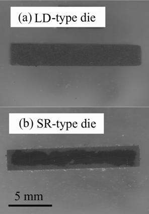
Figure 7. Typical cross-sectional views of fine Ni-20Cr bodies produced by PECS at 700°C of die temperature with SR die (a) and the LD die(b). Table 3. Summary of cross-section observation by using SEM | | | SR | ○ ○ ○ | ○ × × × × | × × × | | LD | - | ○ ○ ○ ○ ○ | × × × | “○” homogeneous microstructure, and “×” inhomogeneous microstructure Figure 8 shows the cross-sectional scheme of a porous sample. The outside and inside regions, as shown in Figure 8, were observed by using SEM. Figure 9 shows typical cross-sections of the samples sintered at 700°C of die temperature with SR die. The microstructures of the samples made of the coarse powder are homogeneous as shown in Figure 9(a). Figures 9(b) and (c) represent microstructures of the homogeneous and inhomogeneous one, respectively, in the samples made of fine powder. Figure 10 shows a typical cross-section of the samples made of the fine powder sintered at 700°C with LD die. The microstructure is homogeneous. 
Figure 8. A cross-sectional scheme of porous sample 
Figure 9. Cross-sectional views of Ni-20Cr bodies sintered by PECS with SR die for 5 min at 700°C of die temperature. a) 70 µm particle size and b), c) 5 µm particle size 
Figure 10. Cross-sectional views of Ni-20Cr (5 µm) bodies sintered by PECS with LD die for 5 min at 700°C of die temperature. Discussion Relative Density The samples made of fine powder have poorer homogeneity in density than ones using the coarse powder. This phenomenon can be explained by the temperature dependence of sintering rate and the temperature distribution of sample during PECS process. Neck growth in the Initial stage of sintering can be expressed as:  (1) (1)
where x is neck radius, a particle size, A and m constants, k mass transport parameter corresponding to sintering mechanism, such as creep strain rate or diffusion coefficient, and t time. Linear shrinkage (Δl/l0) can be expressed as:  (2) (2)
That is,  (3) (3)
where n is a constant depending on sintering mechanism. Equation (3) means that densification rate increases as decreasing in the particle size. This is commonly observed in sintering process and is observed in this work as seen in Figure 6. Decreasing particle size of powder also enhances influence of mass transport parameter to densification rate, as shown in Eq. (3). When the temperature in the inside of sample is higher than that at the outside, mass transport parameter in the inside is also higher than that at the outside. In the punch-compressing direction, punch temperature is lower than the sample inside because the punches are in contact with water-cooled rams. Such temperature distribution of sample during PECS has been reported previously [13-16]. The difference in densification rate between the inside and the outside is enlarged with decrease in particle size. Since densification of porous bodies decreases its electric resistivity, Joule heating of the inside with higher density is larger than the outside, and enhances the temperature distribution in the sample during the PECS process. This process will accelerate densification in the inside in comparison with the outside, for fine powder. Ozaki et al. [10] described densification distribution of sintered Al powder with less than 10 μm in particle size during the PECS process. They investigated microstructure of sintered Al bodies sintered by PECS at constant electric current. In the initial stage of the PECS process, the center part was densified more than the outside. According to them, their fine Al powder has highly oxidized and has higher electric resistivity. Since concentration of electric current to the sample does not occur in their PECS process, temperature of die is higher than the sample. This means that heat transfers from die to sample during PECS process. Temperature distribution of Al sample in their study must be reverse of the present case with Ni-20Cr powder. Improvement of Homogeneity of Density As described previously, use of LD die gives porous samples with more homogeneity. This must be due to the reduction in temperature distribution of the sample by using LD die. The electric resistance of graphite of die, is 1.5×10⁻⁵ Ω m (data from the supplier). The bulk resistance of Ni-20Cr is 1×10⁻⁶ Ω m [17]. At the initial stage of sintering, the electric resistance of the sample is higher than the value of dense one. The electric resistivity of a partially sintered body with 0.7 in relative density measured by 4-probe method at room temperature was comparable with the value of graphite. Both sample and die are heated by Joule heating during PECS process. Sample surface temperature should be higher than the die temperature, since heat transfers from the sample to the die. Figure 11 represents the schematic drawing of temperature distribution of sample and SR and LD type dies during PECS process. A thicker die wall must reduce heat transfer from sample and as a result temperature gradient decrease. Temperature gradient from the sample center to the die surface becomes smaller for the die with thicker die wall. 
Figure 11. Temperature distributions of sample center and die surface during PECS
(x2 >> x2’) Less reproducibility of homogeneity in the samples made by using the SR die, as represented in Table 3 and Figure 9, may be given by difference in powder packing or punch/die gap in each sample, causing different distribution of electric current in each sample. Use of the SR die will give poor reproducibility of homogeneity of samples by enhancing such small difference in each sample, as discussed above. Conclusions Ni-20Cr powders with 5 μm and 70 μm in particle size were partially sintered to produce porous bodies by PECS process using graphite dies with different geometry: PECS-supplier recommended type (OD:φ30(ID:φ15)×30) and dies with large outer diameter. The sintering was carried out at temperatures ranging from 600 to 750˚C of die temperature for 5 min under 13 MPa in uni-axial pressure. There was no significant difference in relative density with different die size and shape. Densification rate of the fine powder was higher than the coarse one. Microstructure of porous Ni-20Cr made of the coarse powder was homogeneous under all sintering conditions. In the case of the fine powder, the sample inside was significantly denser than the outside. The heterogeneity of partially sintered bodies made of the fine powder was explained by temperature distribution and temperature dependence of densification rate. Microstructure of porous bodies becomes homogeneous by using the die with thicker die wall. Increasing the die temperature, heterogeneous structure appears, even using the thicker die. Reproducibility of the microstructure of fine metal powder was lower than the coarse powder, and becomes higher by using the die with thicker die wall. Acknowledgements The authors wish to express their gratitude to the Japanese government for partially supporting this work through the 21st Century Centers of Excellence (COE) Program of the Ministry of Education, Culture, Sports, Science and Technology. References 1. M. Tokita, “Trends in Advanced SPS Spark Plasma Sintering Systems and Technology”, J. Soc. Powder Technol. Jpn., 30 (1993) 790-804. 2. H.Oonishi, Y. Ikarashi and M.Nanko, A. Kondo, T. Nagai and K. Ishizaki, “Applications of Spark Plasma Sintering –Production of Porous Materials and Intermetallic Compounds”, New Materials, 7 (1996) 34-37. 3. K. Ishizaki, S. Komaneni and M. Nanko, Porous Materials, Kluwer Academic Publishers, Netherlands, pp. 52-56 (1998). 4. M. Nanko, H. Onishi and K. Ishizaki, “New Sintering Processes for Porous Materials”, Ceramic Industry, 145 (1996) 31-37. 5. M. Oomori, “Sintering, Consolidation, Reaction and Crystal Growth by the Spark Plasma System (SPS)”, Mater. Sci. Eng., A287 (2000) 183-188. 6. O. Yanagisawa, T. Hatayama and K. Matsuki, “Recent Research on Spark Sintering Process”, Materia Jpn., 33 (1994) 1489-1496. 7. M. Oomori and T. Hirai, “The Spark Plasma System (SPS) as an Advanced Material Synthesis”, Mate. Sci. Technol., 40 (2003) 138-142. 8. Y. Kouno, M. Kawahara and M. Tokita, “Sintering of Porous Bodies Prepared by Spark Plasma Sintering (SPS)”, Proc. SPS Kenkyu-Kai, 4 (1999) pp59-60. 9. M. Nanko, T. Maruyama and H. Tomino, “Neck Growth on Initial Stage of Pulse Current Pressure Sintering for Coarse Atomized Powder Made of Cast-Iron”, J. Jpn. Inst. Metals., 63 (1999) 917-923. 10. K. Ozaki, K. Kobayashi, T. Nishio, A. Matsumoto and A. Sugiyama, “Sintering Phenomena on Initial Stage in Pulsed Current Sintering”, J. Jpn. Soc. Powd. and Powd. Metall., 47 (2000) 293-297. 11. M. Nanko, K. Matsumaru and K. Ishizaki, “”, Inhomogeneity of Sintered Bodies Prepared by Pulsed Electric Current Sintering”, Proc. SPS Kenkyu-Kai, 7, pp82-83 (2002). 12. M. Nanko, M. Sato, K. Matsumaru and K.Ishizaki, “Homogeneity of Porous Metals Prepared by Pulsed Electric Current Pressure-Sintering”, Proc. MAPEES’04, submitted. 13. T. Abe, S. Sumi, H. Hashimoto and T. Kuriyama, “Material Characterization by Ultrasonic Imaging”, Materia Jpn., 35 (1996) 804-809. 14. H. Tomino, H. Watanabe and Y. Kondo, “Electric Current Path and Temperature Distribution for Spark Sintering”, J.Jpn Soc. Powd. and Powd. Metall., 44 (1997) 974-979. 15. S. Sumi, Y. Mizutani and M Yoneya, “Temperature Measurement of the Mold and Samples on the Pulse Plasma Sintering”, J.Jpn Soc. Powd. and Powd. Metall., 45 (1997) 153-157. 16. H. Tomino, H. Watanabe and Y. Kondo, “Study on Temperature Distribution and Electric Current Path for Pluse Electric Current Sintering”, Adv. Tech. Mater. Mater. Proc. J., 1 (1988) 34-41. 17. K. Ando, Denki-Densi-Zairyo, ed. by H. Hirai, K. Narita, M. Ieda, Y. Inuishi, K. Ando and Y. Hamakawa, Ohm-Sya, Tokyo, pp. 273-274 (1991). Contact Details | Manabu Sato Department of Mechanical Engineering
Nagaoka University of Technology
Nagaoka
Niigata 940-2188, Japan | Makoto Nanko Department of Mechanical Engineering
Nagaoka University of Technology
Nagaoka
Niigata 940-2188, Japan Email: [email protected] | | Koji Matsumaru Department of Mechanical Engineering
Nagaoka University of Technology
Nagaoka
Niigata 940-2188, Japan | Kozo Ishizaki Department of Mechanical Engineering
Nagaoka University of Technology
Nagaoka
Niigata 940-2188, Japan | |