Introduction Oxide dispersion strengthened (ODS) alloys are extensively used for heat resisting applications (e.g. turbine components, tubing in heat exchangers etc.) because of their very high mechanical strength and corrosion resistance properties at elevated temperature. In order for these alloys to be used to fabricate components for use in critical applications, suitable joining techniques need to be developed with the ability to minimize damage to the unique microstructure of these alloys. Transient liquid phase (TLP) diffusion bonding has been of interest as an alternative joining method for advanced alloys when neither fusion welding nor solid-state bonding techniques are successful [1]. In TLP bonding an interlayer containing melting point depressants is placed between the bonding surfaces. At the bonding temperature, which is less than the melting temperature of the parent alloy, the interlayer melts and changes in composition of the liquid interlayer (due to the loss of melting point depressants from the joint region) results in the formation of a joint by isothermal solidification. However, earlier research has shown that the hard and brittle intermetallic phases, which have been shown to be detrimental to the mechanical properties of joints, are often formed across the joint region in the TLP bonding process [2]. The composition of interlayer is one important parameter which can solve the problem associated with the formation of deleterious intermetallic phases and thus the selection of interlayer composition is critical to the TLP bonding process. Although considerable research has been carried out to study the effect of interlayer composition on TLP bonding behavior for traditional alloys, very little has been done to the study of the effect of the same for ODS superalloys. Therefore, the objective of this research work was to investigate the effect of interlayer composition on microstructural developments across TLP bonded joints made using a nickel ODS alloy. Different nickel based interlayer compositions were studied and included; MBF 80 (Ni-Cr-B), MBF 15 (Ni-Cr-Co-Fe-B-Si), Ni-P and MBF 50 (Ni-Cr-Si-B). The influence of hold time at the bonding temperature and the use of post-bond heat treatments on compositional and microstructural homogeneity across the joint region are reported in this communication. Experimental Procedure The fine-grained (1-2 µm) Inconel MA 758 was joined in the as received condition. The nominal composition of the alloy in mass% was Ni-bal., 30-Cr, 0.3-Al, 0.5-Ti, 0.6-Y2O3, 1.0-Fe, and 0.05-C. All specimens to be bonded were cut to a dimension of 10 x 10 x 5 mm from the hot finished circular plate. The joining surfaces were prepared by grinding down to 600-grit SiC paper finish to ensure flatness. Prior to bonding operation, specimens were cleaned in acetone. The commercially available nickel based interlayers in the form of thin foils were used for TLP bonding. The compositions of the interlayers in mass% are given in table 1. Table 1. Nominal composition of the interlayers, mass% | | | MBF 80 | Bal. | 15.2 | - | - | 0.06 | - | 4.0 | - | | MBF 15 | Bal. | 13.0 | 1.0 | 4.2 | 0.03 | 4.5 | 2.8 | - | | Ni-P | Bal. | - | - | - | - | - | - | 8.28 | | MBF 50 | Bal. | 19.0 | - | - | 0.08 | 7.3 | 1.5 | - | The joining process was performed in an induction heating furnace with the vacuum of 0.053 N/m2. A minimum bonding pressure of 196 kN/m2 was applied to keep the bonding surfaces in an intimate contact. The bonding times used for this experiment are 120, 900 and 1800 seconds. Depending on the melting temperature of interlayers the bonding temperatures of 1393 K, 1378 K, 1273 K and 1443 K were used for; MBF 80, MBF 15, Ni-P and MBF 50 interlayer, respectively. The specimens were furnace cooled to room temperature in vacuum once the holding time was completed. For metallographic examination, the bonded samples were sectioned through the joint region and one half of each bonded sample was then heat treated using a temperature of 1633 K for 7200 seconds. All specimens were prepared using standard methods of metallographic preparation which includes grinding surfaces down to a 1000-grit SiC paper finish, followed by polishing with diamond fluid to a 1 µm finish. The chemical etchant was prepared by mixing 1 part of H2O2, 2 parts of concentrated HCl, and 2 parts of distilled water just before etching. The joint region was examined using light and scanning electron microscopy (Jeol JXA-8200). The changes in the composition of the bond interface were examined using energy dispersive x-ray spectroscopy (EDS). Micro-hardness testing was done to assess the homogeneity of the bond region using a Leitz Mini-load microhardness tester with a load of 0.49 N. Results and Discussion Microstructural Analysis Metallographic examination of the joints showed that the hold time had an effect on the rate of isothermal solidification during the TLP bonding process. The micrographs of joints made using all four interlayers for 120 seconds hold time produced eutectic structures at the joint centre. The SEM micrograph in figure 1 shows these centerline eutectic structures for the joint made using Ni-P interlayer. This suggested that the diffusion away of melting point depressants from the joint region was not completed for a bonding time of 120 seconds. Therefore, sufficient compositional change within the joint region did not occur to complete isothermal solidification of the liquid interlayer. The centerline eutectic structures were induced by the eventual transformation on cooling of the residual liquid present at the end of the 120 seconds hold time. For a hold time of 900 seconds, the eutectic structure was still observed for joints made using MBF 15, MBF 80 and Ni-P interlayers. However, the amount of these structures observed for 900 seconds hold time was much less (see figure 2a) than that for a 120 seconds hold time. This suggested that a longer hold time was required for completing isothermal solidification. However, an isothermally solidified joint was produced for 900 seconds hold time when MBF 50 interlayer was used. This interlayer contained the least amount of B (see table 1) and appeared to show complete isothermal solidification with a joint free of centerline eutectic structures, see figure 2b. 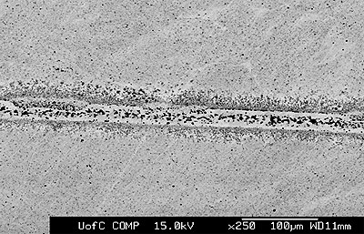
Figure 1. SEM micrograph of joint made using Ni-P interlayer for 120 seconds hold time. 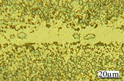
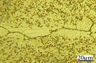
Figure 2. Light micrographs of joints made for 900 seconds hold time a) Ni-P interlayer b) MBF 50 interlayer. Micrographs of joints made using MBF 80, MBF 15, Ni-P and MBF 50 interlayer compositions for an 1800 seconds hold time are shown in figures 3(a)-(d), respectively. These micrographs show that joints free from eutectic structure at the joint center were produced in all cases. This suggested that the joint free from centerline eutectic structures can be produced in TLP bonding technique by optimizing the bond time. However, segregation of intermetallic precipitation was identified adjacent to the joint interface for bonds made using all four interlayers. Figure 4a shows the intermetallic precipitates adjacent to the joint interface for bond made using MBF 15 interlayer. EDS compositional analysis suggests that these precipitations are consisted of nickel and chromium rich boride when joints made using MBF 80, MBF 15, and MBF 50 interlayer. Figure 4b shows the composition of intermetallics adjacent to the bond interface when using MBF 15 interlayer (as a results of the limitation of the EDS analytical software in quantifying light elements with atomic number less than 10 boron is not seen in the spectrum). The density of these precipitates gradually reduced with increasing distance from the bond line (figure 4a). Gale and wallach[3] reported a significant precipitation of nickel boride in the region close to the interlayer/parent metal interface when TLP bonding of Ni using Ni-B-Si interlayer. In their work on diffusion brazing of Inconel 738 using NB 150 insert, Chaturvedi et al.[4] suggested that the formation of Cr(Ni) boride precipitations are attributed as a result of boron diffusion exceeding the solubility limit at the bonding temperature during the initial stages of joint formation. In this work, however, the least amount of intermetallic precipitations observed adjacent to the joint interface when bonds made using MBF 50 interlayer containing the least amount of boron. It is commonly believed that, for optimum bond quality the amount of boron in an interlayer composition should be at a level which fully saturates the grain boundaries in a superalloy but does not allow the formation of boride precipitations. It is worth mentioning that, for bonds made using MBF 50, close examination revealed grain growth occurring within the joint region and this had the effect of breaking up the distinct bond-line and offered some continuity within the parent grain structure. As was mentioned earlier, the isothermal solidification time was shorter for bond made using MBF 50 interlayer. This means a relatively longer time was employed for homogenization for this particular bond among the bonds made using all four interlayers with an 1800 seconds hold time. The grain growth within the joint region for bond made using MBF 50 was thought to be attributed to this factor. 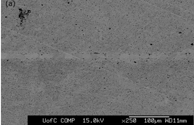
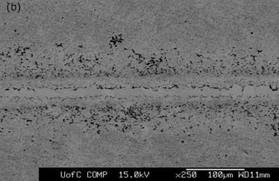

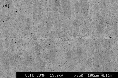
Figure 3. SEM micrographs of joints made for 1800 seconds hold time using interlayers: a) MBF 80 b) MBF 15 c) Ni-P d) MBF 50. 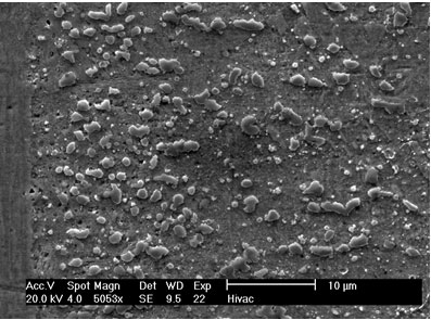
Figure 4. Intermetallic precipitates adjacent to the bond interface when using MBF 15 interlayer: a) SEM micrograph b) Composition profile of the intermetallics. In the case of joints made using Ni-P interlayer for 1800 seconds hold time, a wide band of intermetallic precipitations adjacent to the joint interface were identified (figure 3c). EDS analysis showed high intensity peaks for P, Ni and Cr, as shown in figure 5a. This suggested that these precipitates could be phosphides of Cr and Ni. The formation of phosphides was found to occur during the dissolution and isothermal solidification stages because precipitates formed not only along the joint interface, but also within the parent alloy. Although the solubility of P in Cr is very limited (about 0 mass% at 1273 K), the solubility of P in Ni-Cr is much higher (≥ 14 mass% at 1273 K). Nakagawa et al. (1991) did not observe phosphides when studying the TLP bonding of Ni/Ni-14%Cr-10%P/Ni system [5]. This suggested that a high Cr content (e.g. ~30 mass% as in this study) was necessary for the formation of phosphides. In order for such a high Cr content to build up within the liquid interlayer, a rapid diffusion of Cr from the parent alloy into the liquid interlayer would be necessary. It is suggested that local equilibrium was not established across the solid/liquid interface, and Cr was free to diffuse from the parent alloy into the liquid interlayer immediately during melting of the parent alloy. The continuous Cr diffusion results in a P concentration in excess of the P solubility in Ni-Cr, which would than result in the formation of phosphides. 
Figure 5. EDS analysis taken from the bond interfaces when using a Ni-P interlayer (1800 seconds hold time): a) before post-bond heat treatment b) after post-bond heat treatment. Homogenization of the joint is important for the high temperature performance of ODS alloys [6]. To introduce the microstructural and compositional homogenization TLP bonded samples were post-bond heat treated. The results showed that the use of post-bond heat treatment was successful to dissolve the hard intermetallic precipitation adjacent to the joint interface for bonds made using all four interlayers. A comparison of EDS compositional analyses before and after heat treatment of the joints made using Ni-P interlayer in figures 5(a) and (b) clearly show that the heat treatment removed the phosphide precipitates from the joint interface. This heat treatment was also successful in producing a continuous microstructure across the joint region as shown in figure 6. However, closer examination of the bonded region also reveals a slight difference in grain size between that of the joint and parent metal. The “fine grain zone” width corresponds with the width of intermetallics formed during the bonding stage (see figure 3c). The Ni-P binary phase diagram[7] indicates that the dissolution temperature for nickel phosphide precipitates is between 973-1433 K (dissolution temperature of chromium phosphides is assumed to be less than 1633 K). This suggests that when these phosphides go into solution the phosphorus is “free” to diffuse away. However, the hypothesis is that this “free phosphorus” also results in some melting at grain boundaries, which in turn, results in the unpinning of grain boundaries from the Y2O3 dispersion and some grain growth within the joint region. Once the sample reaches the heat treatment temperature of 1633 K, the parent metal recrystallizes to form a large grain structure, but grains at the joint region have lost the critical energy necessary for further grain growth. A similar observation was recorded by Khan et al. [8] in their work on joining ferritic ODS alloys. 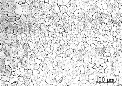
Figure 6. Micrograph of joint made using Ni-P interlayer for 1800 seconds hold time followed by a post-bond heat treatment at 1633 K, 7200 seconds. Micro-Hardness Analysis The degree of compositional homogeneity achieved across the joint region was assessed by micro-hardness testing. A uniform value of hardness across the joint would indicate good homogeneity. Micro-hardness profiles measured as a function of distance from the centre of the joint can be seen in figure 7. The four curves in figure 7a correspond to the micro-hardness profiles for bonds made using the four different interlayer compositions. The highest hardness values of 490 VHN, 410 VHN and 400 VHN for Ni-P, MBF 80 and MBF 15 interlayer, respectively were measured at the interface of the joints and approximately 30 to 40 µm from the joint centre where intermetallics had formed during the bonding process. The least scatter in hardness values was recorded for joints made using the interlayer MBF 50. This result also corresponded to the microstructural observations where almost no intermetallic precipitate formation was seen at the joint interface. Figure 7b shows the differences in hardness profiles before and after post-bond heat treatment. The peak hardness values adjacent to the joint interface decreased significantly after post-bond heat treatment and this corresponds to the dissolution of hard intermetallic phases after post-bond heat treatment. In all cases the hardness values for the heat treated bonds decreased due to an increase in grain size and became uniform within the parent alloy. According to the Hall-Petch relationship the hardness of a fine grain structure would be higher than a coarse grain structure. However, in contrast to this relationship, a lower hardness value was measured at the centre of the joint. It is suggested that the load used for micro-hardness testing (0.49 N) is not small enough to be able to compare the effect of strain hardening due to differences in grain size between the joint and parent metal. Therefore, the micro-hardness results are a measure of compositional changes due to solid solution strengthening across the joint. However, the lower hardness values at the centre of the joints indicated that full compositional homogenization was not completed. This in turn suggests that the mechanical properties of the joint region will differ from those of the parent alloy. 
Figure 7a. Hardness profiles of bonds made with 4 different interlayers. 
Figure 7b. Hardness profiles of bonds, before and after heat treatment. Conclusions TLP diffusion bonding technique was used to join MA 758 using MBF 80 (Ni-Cr-B), MBF 15 (Ni-Cr-Co-Fe-B-Si), Ni-P and MBF 50 (Ni-Cr-Si-B) interlayers. This preliminary study revealed that a bonding time of 120 seconds is insufficient to produce a joint by isothermal solidification irrespective of the interlayer used. All interlayers except MBF 50 produced joints with centerline eutectic structures for a bonding time of 900 seconds. The formation of intermetallic precipitations adjacent to the joint interface were observed for bonds made using all four interlayers with a bonding time of 1800 seconds. However, the amount of intermetallic precipitations observed when bonding using the MBF 50 interlayer was much less suggesting that the composition of this interlayer is best suited for TLP bonding MA 758. The results indicated that the use of post-bond heat treatment at a temperature of 1633 K was successful in removing precipitation at the joint and for encouraging grain growth across the bonded interface. Acknowledgements The authors wish to thank NSERC, Canada for financial support for this work. References 1. L. E. Shoemaker, “Joining Techniques for Ferritic Oxide Dispersion Strengthened Alloys”, proceedings of the International Conference on Trends in Welding Research, Gatlinburg, TN, USA, ASM International, 371-377, May 1986. 2. E. Lugscheider, H. Schmoor and U. Eritt, “Optimization of Repair-brazing Processes for Gas Turbine Blades”, Brazing, High Temperature Brazing and Diffusion Welding, Deutscher Verlag fur Schweisstechnik GmbH, Dusseldorf (Germany), 259-261, 1995. 3. W. F. Gale and E. R. Wallach, “Microstructural Development in Transient Liquid Phase Bonding”, Metall. Trans A, 22A, 2451-2457, 1991. 4. M. C. Chaturvedi, O. A. Ojo and N. L. Richards, “Diffusion Brazing of Cast Inconel 738 Superalloy”, AZo Journal of Materials online, DOI: 10.2240/azojomo0123, 2005. (This paper was also published in print form in Advances in Technology of Materials and Materials Processing, 6 [2] (2004) 206-213). 5. H. Nakagawa, C. H. Lee and T. H. North, “Modelling of Base Metal Dissolution Behavior during Transient Liquid-Phase Brazing”, Metall. Trans. A, 22A, 543-555, 1991. 6. L. J. Park, H. J. Ryu, S. H. Hong and Y. G. Kim, “Microstructure and Mechanical Behavior of Mechanically Alloyed ODS Ni-Base Superalloy for Aerospace Gas Turbine Application”, Advanced Performance Materials, 5(4), 279-290, 1998. 7. ASM Handbook, “Alloy Phase Diagrams”, Metals Park, Ohio, vol. 3, p 313, 1992. 8. T. I. Khan and E. R. Wallach, “Transient Liquid Phase Diffusion Bonding and Associated Recrystallization Phenomenon when Joining ODS Ferritic Alloys”, J. Mater. Sci., vol.31, 2973-2943, 1996. Contact Details |