DOI :
10.2240/azojomo0278
May 3 2009
A. L. Leal-Cruz and M. I. Pech-Canul
Copyright AD-TECH; licensee AZoM.com Pty Ltd.
This is an AZo Open Access Rewards System (AZo-OARS) article distributed under the terms of the AZo–OARS https://www.azom.com/oars.asp which permits unrestricted use provided the original work is properly cited but is limited to non-commercial distribution and reproduction.
AZojomo (ISSN 1833-122X) Volume 5 April 2009
Topics Covered
Abstract
Keywords
Introduction
Experimental
Results and Discussion
Characterization and Thermal Behavior of Na2SiF6
Characterization and Microstructure of HYSYCVD-Si3N4 in Na2SiF6-N2 System
Conclusions
Acknowledgments
References
Contact Details
Abstract
High purity silicon nitride (Si3N4) is required for the production of electronic and optoelectronic devices. CVD is one of the most important synthesis routes for the production of high purity Si3N4. However, the incorporation of hydrogen in the deposition of Si3N4 may negatively affect the properties and quality of deposited material. The hydrogen incorporation has been attributed to the precursors with hydrogen used in the Si3N4synthesis. By CVD typically nitrogen (N2 and NH3) and silicon (silane, halides and metalorganics) are used as precursors, which are either gases or volatile liquids. The synthesis of Si3N4from hybrid precursor (HYSYCVD: hybrid system-chemical vapor deposition) is a new technique that combines solid and gas precursors. HYSYCVD is based on the ability of some solids like sodium hexafluorosilicate (Na3SiF3) to decompose into reduced gas species with higher reactivity than the common precursors as SiF3; it allows forming Si3N4 in N2. The Na2SiF6 salt which is stable and safe at room temperature decomposes on heating at relatively low temperatures (250-600 °C). Therefore it has been successfully applied in the synthesis of Si3N4 by HYSYCVD. The aim of this research is to carry out an extensive study by XRD, DTA/TG, SEM, and EDX, which allows a better understanding of the aspects related with solid precursor decomposition (Na2SiF6) and Si3N4 formation via HYSYCVD. Specifically the thermal and microstructural behavior of Na2SiF6 in nitrogen systems. Results show that the maximum decomposition rate of Na2SiF6 occurs from 522-593°C and that dissociation is hampered in ammonia and improved in nitrogen. Analysis by SEM reveals that before decomposition Na2SiF6 has the appearance of prismatic crystallites and that after dissociation, the morphology changes to fibers. All these transformations take place simultaneously during the synthesis of Si3N4 by the HYSYCVD method.
Keywords
CVD, Si3N4 , Precursors, Synthesis
Introduction
High purity Si3N4 is demanded for the production of electronic and optoelectronic devices. Interestingly, it is highly desirable that the silicon nitride products posses low or null hydrogen incorporation. Although CVD is one of the most useful routes for the synthesis of high purity Si3N4, production of this ceramic only in nitrogen has been too long a challenging task. This is because commonly, conventional CVD processes employ ammonia as one of the nitrogen precursors and silane (SiH4) as one of the main silicon precursors. Other nitrogen precursors are nitrogen or nitrogen-ammonia mixes. The reason why ammonia is preferred over pure nitrogen is because of the high bond dissociation energy of the latter as compared to that for the former. Thus even when using nitrogen-ammonia mixes, hydrogen incorporation into the deposited products by CVD is really difficult to avoid. The reason behind the hydrogen incorporation issue is that hydrogen causes Si3N4-film degradation [1-3]. As for silicon precursors, silane (SiH4) and halides (SiCl4, SiI4, SiBr4, and SiF4,) have been used as gas precursor and metalorganics (tetrametilsilane) as liquid precursors[4]. Although silane and SiCl4 are mostly used as silicon precursors, it is reported that silane is dangerous and SiCl4 tends to form polymers which clog the reactors exit ports [5]. Si3N4 synthesis from silicon solid precursors is a novel method for the production of whiskers, fibers, films/coating and powders recently developed and reported in literature [6]. This method was named by the authors as hybrid precursor systems-chemical vapor deposition (HYSYCVD) or solid/gas precursors-chemical vapor deposition (SOGACVD) because during the synthesis of Si3N4 hybrid precursor systems (solid and gas precursors) are used [6, 7]. This method is based on the ability of some solids like sodium hexafluorosilicate (Na2SiF6) to decompose into highly reactive chemical species that allow producing silicon nitride not only in ammonia, but also in nitrogen. The HYSYCVD method can be considered as an alternative for the synthesis of hydrogen-free Si3N4 [6, 7]. The aim of this research is to carry out an extensive study by X-ray diffraction (XRD), differential thermal analysis-thermogravimetric analysis (DTA-TG), scanning electron microscopy (SEM), and energy dispersive X-ray spectroscopy (EDX), which allows a better understanding of the aspects related to the silicon solid precursor decomposition (Na2SiF6) and Si3N4 formation, focused specifically on the thermal and microstructural behavior of Na2SiF6 in nitrogen containing systems. This particular contribution contains a more comprehensive description of the microstructural evolution of Si3N4 deposits as a function of time and temperature in the Na2SiF6-N2 system.
Experimental
Na2SiF6 decomposition and silicon nitride formation were carried out in a HYSYCVD reactor simultaneously. The processing conditions were: time (0-120 minutes), processing temperature (900-1300°C), substrate temperature (700-1300°C) and pressure (17 to 19 mbars). Ultra high purity nitrogen (99.9999%) was used as nitrogen precursor and Na2SiF6 as silicon solid precursor, respectively. The gas precursors were fed into the reaction chamber at the flow rate of 42-101 cc/min. Thermal analyses under non-isothermal (32-1300°C) and isothermal (360 to 560°C) conditions were carried out in ultra high purity (UHP) nitrogen using a DTA/TGA analyzer. The solid reactants and products were analyzed before and after the thermal decomposition of the salt Na2SiF6 using XRD, SEM, and EDX. Likewise, silicon nitride was characterized by XRD, SEM, and EDX.
Results and Discussion
Characterization and Thermal Behavior of Na2SiF6
Sodium hexafluorosilicate (Na2SiF6) is an odorless, white powder of hexagonal crystals (mol. Wt. 188.06, density 2.679 g/cm3). Results from the thermogravimetric analysis are shown in Figure 1a.
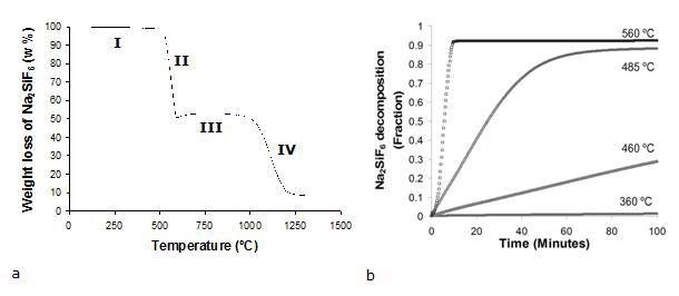
Figure 1. Na2SiF6 decomposition under: (a) non-isothermal and (b) isothermal conditions.
In that figure, it can be seen that the maximum decomposition rate of Na2SiF6 under non isothermal conditions occurs from 522 to 593°C. Four different events are identified in the thermograms for the weight loss of Na2SiF6. The most important event occurs in the temperature range 522-593°C, with a maximum weight loss (50.56 wt.%) and maximum conversion to the gaseous species (89.36 wt.%). This is actually the second event, characterized by a remarkable change in the slopes of the curves at 522°C. The first event, which occurs in the range of temperatures 183-522°C represents barely a weight loss of 2.48 % whilst the corresponding conversion to the gaseous species is 3.1 wt. %. From 593 to 992°C the weight variations are insignificant and hence can be neglected (segment III). Since at approximately 992°C occurs a transition from NaF (s) → NaF (l), the changes in segment IV are attributed to the vaporization of melted NaF. Figure 1b shows plots of Na2SiF6 decomposition fraction as a function of time for various temperatures (from 360 to 560°C) from tests conducted under isothermal conditions. The low temperatures are characterized by a constant decomposition rate, while the high temperatures are distinguished by faster decomposition rates. A slope change (which is more dramatic the higher the temperature) towards a plateau suggests a culmination in the decomposition reaction.
Results from the analysis by XRD of the solids before and after the decomposition of Na2SiF6 are shown in Figure 2. Clearly, before decomposition only peaks corresponding to Na2SiF6 are present, while after the thermal treatment both, Na2SiF6 and NaF are detected. The analysis by SEM of the solids shows that Na2SiF6 has the appearance of prismatic crystallites.
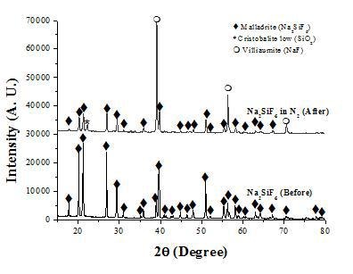
Figure 2. XRD patterns of the solids before and after decomposition of Na2SiF6 in nitrogen.
Then, after the synthesis of Si3N4 by HYSYCVD in nitrogen, the decomposed solids have the morphology of fibers. As illustrated in Figure 3, SEM photomicrographs of the solids before and after decomposition reveal that the Na2SiF6 crystallites have a size between 5-10 µm and that the decomposed solids are fibers with spongy appearance. The changes in solid composition before and after the thermal treatment are evidenced in EDX spectra obtained during the analysis by SEM.
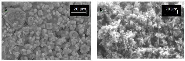
Figure 3a and b. SEM photomicrographs corresponding to: Na2SiF6 synthesized from SiO2 (SiO2 was prepared from rice hulls) before decomposition (left) and, after decomposition (right).
The spectra in Figure 4 show important changes in the global solid composition, indicated by the fluorine and silicon peaks. These changes can reasonably be related with the formation of Si-F chemical species in gas phase. According to these results and to thermodynamic calculations using the FactSage program and databases, it is proposed that during the thermal decomposition of Na2SiF6 not only the gas species SiF4 is produced but also various chemical species with different Si:F ratio.
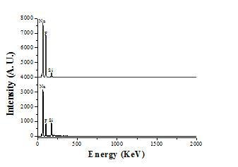
Figure 4. EDX spectra corresponding to the salt before and after decomposition.
In this work it is proposed that the dissociation of Na2SiF6 occurs by means of a set of parallel and consecutive reactions which give place to formation of the highly reactive chemical species SiF4, SiF3, SiF2, SiF, and Si. The parallel reactions represent the formation of all chemical species simultaneously (SiF4, SiF3, SiF2, SiF, and Si) and the successive reactions refer to the dissociation of those chemical species into lower Si:F ratio species (SiF4 → SiF3 → SiF2 → SiF → Si). The dissociation event is then represented as follows:
5 Na2SiF6 → 10 NaF + SiF4 + SiF3 + SiF2 + SiF + Si + 5 F2 ΔG0550 °C=-3,136 kJ.mol-1 (2)
Characterization and Microstructure of HYSYCVD-Si3N4 in Na2SiF6-N2 System
Results from the characterization by X-ray diffraction revealed that silicon nitride was formed both in the α- and β- polymorphs in the system Na2SiF6-N2. Figure 5 is a typical XRD pattern showing the presence of α- and β-Si3N4 in the SiC/Si porous substrate.
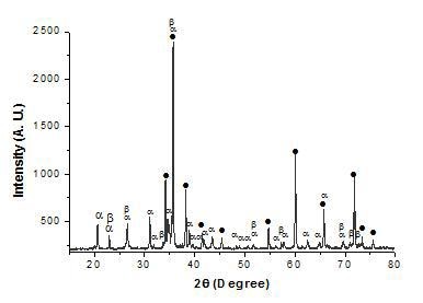
Figure 5. XRD pattern corresponding to HYSYCVD-Si3N4 formed into SiC/Si porous substrates: (α) alpha silicon nitride, (β) beta silicon nitride and (●) silicon carbide.
The photomicrographs in Figure 6 illustrate the typical products obtained in nitrogen at a pressure of 17 mbars for 120 minutes, using a substrate temperature of 700°C. The morphology of the products ranges from fine, soft wool-like fibers and spongy deposits to more compact deposits (see Figures 6a and b). This type of microstructure is typical of materials processed under conditions of low supersaturation and low temperatures.
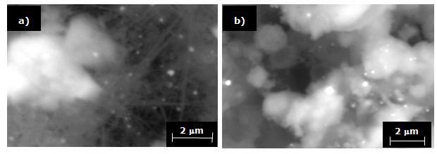
Figure 6. SEM micrographs showing Si3N4 obtained in N2 for 120 minutes and substrate temperature of 700°C. a) Soft wool-like fibers and spongy deposits and, b) Compact deposits.
With an increase in the substrate temperature to 1200°C, the morphology of the deposited phase changes toward soft wool-like fibers, like those shown in Figures 7 a and b.
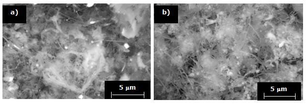
Figure 7. SEM micrographs showing Si3N4 thin-fibers deposited into porous substrates at 1200°C for a) 90 and b) 120 minutes.
It is noteworthy that under the same processing conditions, although the morphology of the phase is similar, a higher quantity of Si3N4 is deposited when time varies from 90 to 120 minutes. This can be observed in the photomicrographs at lower magnifications shown in Figures 8 a and b.
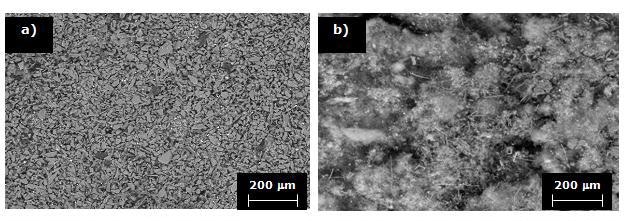
Figure 8. SEM micrographs corresponding to Si3N4 deposited into porous substrates at 1200°C for a) 90 and b) 120 minutes.
In Figures 9 a and b, photomicrographs of specimens processed with the substrate at 1300°C and a processing time of 120 minutes are shown. These figures illustrate that the fibers become larger when the process is carried out in nitrogen atmosphere, at higher temperatures and for longer processing times. In order to confirm the presence of silicon nitride, the specimens obtained by HYSYCVD were also characterized by EDX.
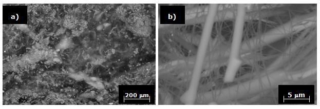
Figure 9. Si3N4 obtained in N2 at 1300°C for 120 minutes.
Figure 10 shows an EDX spectrum corresponding to a sample processed in UHP nitrogen at 1300°C for 120 minutes. This spectrum shows the presence of nitrogen and silicon, thus confirming the presence of silicon nitride in sample processed under this condition. As for microstructural evolution, it was found that in the Na2SiF6-nitrogen system the amount of Si3N4 formed increases with temperature and that the morphology changes from soft and light fibers to thicker and compact fibers.
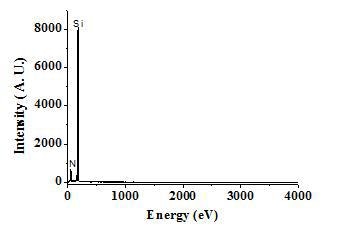
Figure 10. EDX results for HYSYCVD-Si3N4.
According to the results it is proposed that Si3N4 formation occurs by the reaction of highly reactive chemical species (SiF3, SiF2, SiF and Si) generated from Na2SiF6 dissociation or decomposition with nitrogen. Moreover, formation of Si3N4 takes place by means of parallel or similar reactions represented by the next general equation:
3 SiF3 + 3 SiF2 + 3 SiF + 3 Si + 8 N2 → 4 Si3N4 + 9 F2 ΔG01300°C = -1,566 kJmol-1 (3)
Conclusions
The maximum decomposition rate of Na2SiF6 in nitrogen occurs from 522-593°C. Results from the analysis by SEM reveal that before decomposition, Na2SiF6 has the appearance of prismatic crystallites and that after dissociation the solid products have the morphology of fibers. Na2SiF6 dissociates through a series of parallel and successive reactions that give place to highly reactive Si-F chemical species.
Indeed by the HYSYCVD method the chemical species (SiF3, SiF2, SiF and Si) react with nitrogen through a series of simultaneous reactions to form Si3N4 both in the α- and β- polymorphs. Moreover, the amount of Si3N4 formed increases with increase in temperature and the morphology changes from soft and light fibers to thicker and compact fibers.
Acknowledgments
Authors gratefully acknowledge Microabrasivos de México S.A. de C.V. for supplying the SiC powders. Ms. Leal-Cruz thankfully acknowledges CONACyT for providing a scholarship. Finally authors also thank Mr. Felipe Marquez Torres for assistance during the characterization by scanning electron microscopy.
References
1. G. Z. Ran, L. P. You, L. Dai, Y. L. Liu, Y. Lv, X. S. Chen, G. G. Qin, “Catalystless Synthesis of Crystalline Si3N4/amorphous SiO2nanocables from Silicon Substrates and N2”, Chemical Physics Letters, 384 (2004) 94-97.
2. J. Fandiño, G. Santana, L. Rodríguez-Fernández, J. C. Cheang-Wong, A. Ortíz, J. C. Alonso, “Role of Hydrogen on the Deposition and Properties of Fluorinated Silicon-nitride Films Prepared by Inductively Coupled Plasma Enhanced Chemical Vapor Deposition Using SiF4/N2/H2 Mixtures”, J. Vac. Sci. Technol., A 23-2 (2005) 248-254.
3. R. K. Pandey, L. S. Patil, J. P. Bange, D. K. Gautam, “Growth and Characterization of Silicon Nitride Films for Optoelectronic Applications”, Optical Materials, 27 (2004) 139-146.
4. K. L. Choy, “Chemical Vapor Deposition of Coating”, Progress in Materials Science, 36 (1980) 57-170.
5. F. S. Galasso, R. D. Veltri and W. J. Croft, “Chemical Vapor Deposited Si3N4”, Amer. Cer. Bull., 57-4 (1978) 453-454.
6. L. Leal-Cruz and M.I. Pech-Canul, “In Situ Synthesis of Si3N4 from Na2SiF6 as a Silicon Solid precursor”, Materials Chemistry and Physics, 98-1 (2006) 27-33.
7. A. L. Leal-Cruz and M.I. Pech-Canul: Novel Synthesis Method and Characterization of CVD-Si3N4 from Hybrid Precursor Systems: Na2SiF6(s)/N2(g) and Na2SiF6(s)/NH3(g), ICCE-14, boulder, CO. (2006) 328-329
Contact Details
A. L. Leal-Cruz
Centro de Investigación y de Estudios Avanzados Unidad Saltillo
Carr. Saltillo-Monterrey Km. 13. Saltillo, Coahuila, México 25000
E-mail: [email protected]
M. I. Pech-Canul
Centro de Investigación y de Estudios Avanzados Unidad Saltillo
Carr. Saltillo-Monterrey Km. 13. Saltillo, Coahuila, México 25000
E-mail: [email protected]
This paper was also published in print form in “Advances in Technology of Materials and Materials Processing”, 10[1] (2009) 31-38.