Feb 22 2001
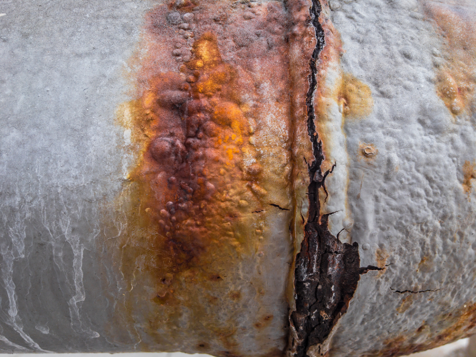
Image Credit: JJSINA/Shutterstock.com
Updated on 3rd February 2020 by Jo Finchen Parsons.
The effects of residual and applied stresses and corrosive environments in service are closely interrelated. The more highly stressed (higher energy) regions of a metal will become anodic, and corrosive cells will emerge from differences in local stress levels.
Cold-worked regions, for example, tube or sheet bends and cut edges, will be corroded in preference to uniform sections just as grain boundaries are attacked more than grain interiors on the microscopic scale.
Stress Corrosion Cracking (SCC) Defined
The combined effects of stress and corrosion can cause a special type of failure known as Stress Corrosion Cracking (SCC). This arises under specific circumstances for a given alloy: specific alloy condition, plus specific corrosive media, and sufficient local tensile stress.
Chloride induced cracking of stainless steels, caustic cracking of plain carbon steels, and ammonia damage to copper alloys are typical examples of this problem. The mechanism of SCC is shown as a simple representation in Figure 1.
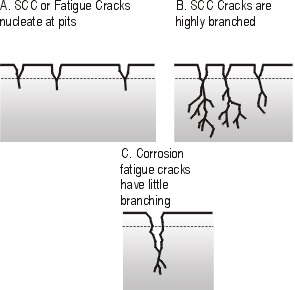
Figure 1. Schematic view of Stress Corrosion Cracking (SCC) and corrosion fatigue cracking.
SCC is believed to be nucleated at pitting damage sites and develops under local tensile stresses as a highly branched network of fine cracks. At each crack tip, the combined action of the tensile stress and specific ions in the corrosive media cause continual crack propagation with little evidence of local deformation.
In austenitic stainless steel, for example, warm chloride solutions in the presence of residual tensile stress can lead to cracking. SCC tendency is slight in low Ni ferritic and martensitic grades but is severe in the 8–10% Ni austenitic steels. Duplex stainless steels have greater SCC resistance than austenitic since the duplex microstructure helps to inhibit the growth of SCC cracks. These tend to be deflected or arrested at austenite-ferrite interfaces.
The maximum resistance is obtained with 50/50 austenite-ferrite microstructures and the dispersion of the two phases should be as fine as possible. The increased interest in the duplex grades stems not only from their high pitting and SCC resistance but also from their higher proof stress levels which offer savings in material and weight over austenitic material.
When does SCC Occur?
Stress corrosion cracking presents an especially difficult problem, since not only is it highly localized but it can occur in environments that are only mildly corrosive to the material. The damaging concentration of the harmful ions in that environment may be quite small and difficult to detect. Even in the absence of applied stress, residual stresses in a structure can often be of a sufficiently high level to cause SCC and failure in service.
The time of exposure needed to cause SCC failure depends on the stress intensity at any pre-existing or developed crack tip. The concentration of stress at the tip of a sharp crack or flaw can be quantified in terms of the Stress Intensity Factor, K1. It determines the growth rate of SCC cracks for a specific alloy–environment combination.
Catastrophic failure of a component occurs when this factor reaches a critical value, the fracture toughness of the material, K1C. Knowing the Stress Intensity Factor allows the calculation of tolerable defect size in design to avoid failure under given loading conditions.
Below a threshold value of K1, called K1SCC, growth of a crack by SCC is not expected, but above this value, the initial SCC growth rate climbs with increasing K1, called stage 1 cracking, Figure 2.
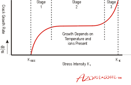
Figure 2. Growth rate of SCC cracks.
In stage 2, the crack growth rate is independent of K1 and depends instead on the corrosive environment and temperature. During stage 2 growth, K1 continues to increase and this leads to the rapid acceleration of the crack in stage 3, and final fast fracture when K1 reaches K1C which is the fracture toughness of the material.
The higher the value of K1SCC under given conditions, then the greater the expected SCC resistance, but some materials do not appear to have a threshold resistance.