Ductile Machining of Brittle Materials
Hard and brittle materials such as glasses and ceramics are amongst the most difficult to machine. The increasing requirement for precise and complex shaped components produced in a variety of ‘brittle’ materials has resulted in a need for more controllable and repeatable manufacturing methods. Material removal processes are typically based around diamond turning or diamond grinding. A key requirement is the ability to control surface integrity during machining processes whilst maximising material removal rates and minimising production cost. Important surface integrity issues include surface finish, residual stress and localised microfracture / microstructure effects. This has placed arduous requirements on both the machine tools and the associated tooling. Higher precision machine tools have been developed and tool preparation methods have been improved.
The material removal process can be considered broadly in terms of fracture dominated mechanisms or localised plastic deformation. For conventional machining of brittle materials, fracture processes result in localised surface damage that may compromise material properties and performance. For many applications this surface damage must be removed by lapping and polishing processes which tend to be time consuming and expensive whilst also possibly compromising form accuracy. To address this problem much effort has been put into the development of ‘damage free’ or ‘ductile regime’ machining. The ability to manufacture high quality surfaces is becoming more reliant on processes such as ductile machining. Basic research into ductile machining of brittle materials has demonstrated that hard materials can be machined, albeit at low tool penetration levels, with ductile type removal mechanisms and that surface and sub-surface damage can be minimised.
The concept of ductile mode machining is based on the observation that localised plastic deformation can occur in brittle materials within a small controlled volume at the tool – workpiece interface before any fracture occurs. Blake and Scattergood have proposed that there is a true size effect for fracture initiation, since the energy of plastic deformation scales with deformed volume, whereas the energy of fracture scales with crack surface area [1]. Therefore plastic deformation becomes energetically favourable as the scale of deformation decreases, and hence there is a volume below which material will deform plastically and not fracture. This has led to the development of theoretical models which predict the "critical depth of cut", which is assumed to be a function of the deformed volume, that results in brittle fracture.
The ability to predict optimum machining conditions and the safe envelope of operating parameters is essential if effective machining processes are to be developed. To predict ‘ductile regime’ machining conditions considerable effort has been focussed on relating the on-set of surface and sub-surface damage during machining to quasi-static indentation. An indentation fracture mechanics approach can be used to predict the on-set of fracture based on small scale indentation events to simulate tool/abrasive – workpiece interactions.
Deformation/fracture diagrams normalised with respect to hardness and fracture toughness [2] are useful in identifying the critical load for the on-set of fracture. Below this critical load the tool/workpiece interaction is deformation controlled and no fracture damage is observed. The concept of a critical load can be extended to chip thickness. As the chip thickness increases the load should also increase for a given contact situation. It should therefore be possible to relate a critical load for the on-set of fracture to a critical chip thickness or equivalent depth of penetration.
Bifano's critical chip thickness model [3] uses a fracture mechanics approach and is developed from indentation studies together with data generated from diamond grinding trials. The critical depth of penetration for initiating fracture is given by [2]
 (1) (1)
where
dc is the critical penetration depth for fracture initiation
ψ is a dimensionless constant depending on indenter geometry
E is the Young's Modulus
Results from the ductile mode grinding of glass have been used to calculate a value for ψ by correlating measured values to the calculated critical depth predicted by equation 1. The point of transition to brittle fracture can be arbitrarily defined as a surface exhibiting 10% of surface fracture and 90% of apparent ductile removal during grinding [3]. The critical depth is then given by:
 (2) (2)
The critical depth of cut, or more accurately chip thickness, for different types of glass predicted by this method is typically 10 – 100 nm.
Diamond Turning
Tani et al have carried out diamond turning experiments on BK7 glass which show that the critical depth of cut to brittle fracture was in fact less than 100 nm for glass [4]. Research into ductile mode turning of materials used for infrared optical elements has concentrated on optical germanium and silicon. Early work by Gerchman and McLain on high quality germanium, produced diamond turned surfaces having a surface finish of 5-6 nm Ra [5]. The material removal rate (expressed as feed per revolution of the workpiece) was 2.5 µm/rev and the applied depth of cut was relatively large, being 25 µm.
This would suggest that the critical depth of cut to provide ductile turning in silicon and germanium is between 1 and 2 orders of magnitude greater than that proposed by others for glass materials. However, it is the tool geometry together with the material mechanical properties which contribute to the significant difference [1]. The effective depth of cut or effective chip thickness is shown schematically in Figure 1 which illustrates the cutting geometry when conventional radius tools are used. The chip cross section has a varying effective thickness teff as shown in Figure 2. When tool radius (R) is much larger than the tool feed per revolution of the workpiece (f), the maximum uncut chip thickness (tm) is most greatly influenced by feed per revolution. This is particularly important since feed rate determines the material removal rate for rotationally symmetric components and hence the total machining cycle time.
Blake and Scattergood have also studied the transition from ductile to brittle fracture using an “interrupted cut method” [1]. A fast tool servo was used to retract the tool rapidly from the surface of the workpiece to reveal the uncut shoulder region. This region was observed using an optical microscope to assess the point along the shoulder where transition from ductile to brittle fracture occurred. Knowing the machining parameters and tool geometry involved in each test, the critical chip thickness (dc) for the onset of brittle fracture could be calculated. This demonstrated that a ‘damage free’ surface was not necessarily produced solely by a ductile mode of material removal. In fact ductile mode turned surfaces in silicon and germanium were found to be produced by a combination of brittle fracture and ductile mode removal mechanisms. This is shown in Figure 1. True ductile mode machining probably only occurs near the apex of the tool and the critical chip thickness (dc) can be defined as that which does not propagate fracture damage beyond the finished surface plane of the workpiece.
|
|
|
Figure 1. Diamond machining cutting geometry [1].
|
From this basis equation 4 can be used to predict the maximum feedrate (fmax) for a given tool such that microfracture damage does not propagate below the cut surface plane.
 (4) (4)
where dc is the critical chip thickness, yc is the depth of surface damage and R is the tool radius. Another important finding from this work was that the nominal depth of cut (d), as shown in Figure 2, has little effect on the critical chip thickness.
|
|
|
Figure 2. Chip cross section illustrating chip thickness [1].
|
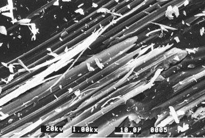
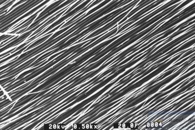
Ruling tests represent a simple method for demonstrating the ductile/brittle response when a diamond indenter slides across a surface. Figures 3 and 4 illustrate the surface appearance of a soda-lime glass when using two different loads. Figure 3 shows the transition from ductile to brittle at a load of around 0.9 N. Figure 4 shows a ductile response when the load is reduced to 0.78 N, a load below the critical value.
|
|
|
Figure 3. Surface of soda-lime glass following ruling test at a load of 0.9N [6].
|
|
|
|
Figure 4. Surface of soda-lime glass following ruling test at a load of 0.78N [6].
|
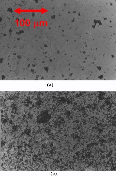
The transition loads for softer ceramics such as PZT materials (Hv~300kg/mm2) are more difficult to identify as the boundary between ductile and brittle behaviour is more diffuse and also depends on local variations in material microstructure and composition. Figure 5 illustrates the surface appearance of diamond turned PZT under two different machining conditions [6]. The critical chip thickness for this material is around 170 nm. Below this value, Figure 5a, ductile material removal is observed although the surface quality is determined by the bulk material characteristics. A surface finish of 11 nm Ra was obtained for the surface shown in Figure 5a but the quality is compromised by the residual porosity within the hot pressed PZT material. Figure 5b illustrates a surface produced using a chip thickness far in excess of the critical value and material removal occurs through a fracture dominated mechanism resulting in a surface roughness of 240 nm Ra.
|
|
|
Figure 5. Diamond turned PZT a) 0.1um depth of cut and feed rate, Ra 11nm, b) 4.9um depth of cut and feed rate, Ra 240nm [6].
|
Even when diamond turning in a ductile mode the cutting forces may be high enough to modify the workpiece material characteristics. In PZT this can be in the form of textural changes which modify the material ferroelectric properties. X-ray diffraction techniques can be used to assess such textural effects and methods using synchrotron radiation have proved useful in determining the depth of ‘damage’ [6]. The example shown in Figure 5a exhibited around 11 µm of damage.
A further issue to be considered is tool wear. Even when maintaining a constant chip thickness tool wear results in an increase in cutting forces. An example is shown in Figure 6 which illustrates the increase in normal cutting force with total cutting distance when diamond turning silicon [7]. In this example the cutting force increases linearly with distance and it was observed that no microcracking occurred below a force of about 0.75 N. Above this cutting force microcracks were observed. The tool radius determined the total cutting length achieved before brittle fracture occurred. This example illustrates the need to monitor forces during the diamond turning process and the benefits that can be obtained by controlling tool wear. Much of the wear associated with diamond tools results from the mechanical-chemical interactions that occur at the tool tip. Control of the thermal characteristics of the process can do much to minimise wear rates and help maintain force levels below the critical value.
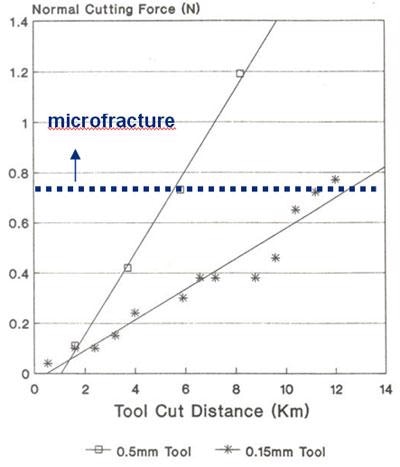
Figure 6. Wear of diamond tools when machining silicon.
The quality of surface finish which can be achieved using modern diamond turning machines is in the range of 1-2 nm Ra (10-20 nm Rt. peak to valley). Form accuracy capability is typically at the 100 nm peak to valley level for optics up to 150 mm diameter.
Grinding Processes
In comparison, with single point diamond turning, ductile mode grinding processes offer the ability to produce optical quality surface finish without significant sub-surface damage at economic removal rates. For example, when used in conjunction with high accuracy machine tools the possibility to finish grind high quality complex shape optics without the need for further finishing operations is becoming a closer reality.
The grinding process can be considered in terms of how individual abrasive grits interact with the workpiece surface. A critical load can again be identified based around the force per grit and this can be related to chip thickness. This chip thickness parameter is dependent on the number of active grinding grits within the grinding zone and the material removal rate. The ability to ensure that each grit produces a chip below the critical thickness depends critically on the machine stiffness and precision. Namba et al claim that the applied depth of cut on the machine can to a great extent be independent of removal mode when machining brittle materials as long as the chip thickness does not exceed a critical value [8]. This has been demonstrated on a range of workpiece materials by Stephenson et al using an ultra-stiff machine tool, Tetraform C [9 -11].
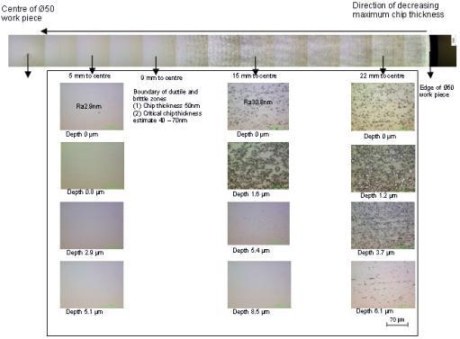
The importance of chip thickness is shown in Figure 7 for the grinding of BK7 glass. In this example a 50 mm diameter BK7 testpiece was ground on a 5 axis Edgetek grinding machine using a resin bond diamond grinding wheel. The workpiece was rotated at 5.5 rpm and the grinding wheel traversed from the outer edge to the centre. Thus the chip thickness varied from a maximum value at the outer edge to a minimum value at the centre. The general surface appearance is shown at the top of Figure 7 and illustrates the sharp transition between ductile and brittle regimes at a position 9mm from the centre. The depth of sub-surface damage can be assessed through a polish and etch technique which highlights the real defect concentration. Examples of the defect levels at different depths are shown in Figure 7 for positions at 5, 15 and 22 mm from the workpiece centre.
|
|
|
Figure 7. Surface and sub-surface damage on ground BK7 glass showing ductile/brittle transition and zero sub-surface damage within ductile grinding regime.
|
This illustrates how the depth of sub-surface damage decreases as the chip thickness decreases. Below the critical chip thickness no surface or sub-surface damage is observed. The critical chip thickness determined from equation 2 for BK7 is 40-70 nm (the range being a function of the variation in measured hardness and fracture toughness). The maximum chip thickness, which depends on the cutting tool geometry, the depth of cut, cutting velocity, and work speed, can be calculated by the expression [12]
 (5) (5)
where Vc is the speed of the wheel; Vw is the work speed; r is ratio of mean chip width to chip thickness; dc is the wheel diameter; ae is the depth of cut; C is the active grit concentration and is estimated as 1.0 × 10⁸ /m2 for the wheel used in the experiments. The value of r is reported to be in the range of 10-20 [12]; r was assumed to be equal to 10 in this study. Equation 5 predicts a maximum chip thickness of 50 nm at the ductile/brittle boundary, a value similar to that predicted from equation 2. Thus, ductile regime grinding conditions can be identified based on the critical chip thickness concept (i.e. the force per grit is below a critical value) and damage free surfaces can be produced that exhibit surface finish in the range 1-3 nm Ra.
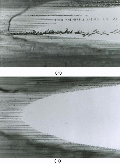
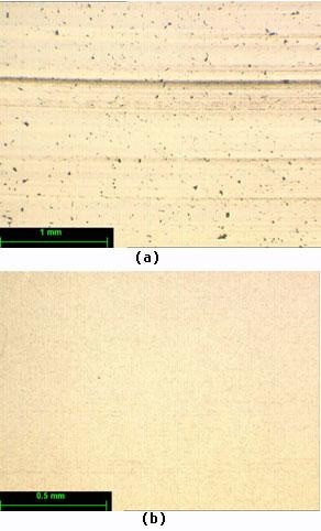
A further example of ductile regime grinding is shown in Figure 8 which illustrates a silicon wafer ground on a wafer face grinder to a surface finish below 10 nm Ra. Figure 9 illustrates a polished taper section through a wafer edge where the critical chip thickness was exceeded in Figure 9a resulting in localised micro-fracture damage. Figure 9b shows a damage free edge ground under ductile regime conditions.
|
|
|
Figure 8. 200mm diameter silicon wafer ductile regime ground to generate high surface quality.
|
|
|
|
Figure 9. Taper section showing ground edge of silicon wafer a) localised microcracking b) damage free grinding.
|
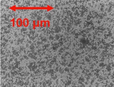
Certain ceramics are more difficult to grind depending on their composition and mechanical properties. PZT is an example where grain pull-out and wheel loading can cause major problems. Figure 10 illustrates a PZT surface ground with a 3-6 µm diamond resin bond wheel, using a 0.1 mm/s feed rate, wheel speed of 30 m/s and depth of cut of 0.5 µm [6]. A poor surface results exhibiting much grain pull-out and a surface finish around 250 nm Ra. Even though the grinding parameters were chosen to give a small chip thickness, the grinding forces soon increased due to the poor cutting efficiency of the abrasive and loading of the grinding wheel with PZT.
|
|
|
Figure 10. PZT ground surface illustrating grain pull-out and poor finish [6].
|
The problem identified in Figure 10 is an example which highlights the dynamic characteristics of the grinding process. Care is taken to true and dress grinding wheels to ensure optimum cutting conditions but the abrasive-workpiece contact conditions continually change due to grit wear, a change in the number of active grits and wheel loading problems. To optimise the grinding process efficiency it is essential to maintain an optimum wheel condition. This can be best achieved through wheel dressing technology.
An important development in dressing technology which has proved suitable for fine grit grinding wheels is that of electrolytic in-process dressing (ELID) [13]. This technique which was developed by Nakagawa and Ohmori [13, 14] was an extension of earlier research carried out by Buttner [15]. The ELID technique ensures that an adequate grain exposure is maintained during grinding. Initially the ELID process was aimed towards applications such as the grinding of silicon wafers but in recent years has been used for a wide variety of ceramic and metallic materials [9, 10, 13, 14].
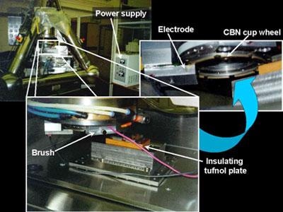
ELID requires a metal bond grinding wheel (for example cast iron), a power supply, a grinding fluid (electrolyte) and an electrode. The metal bond wheel is made the positive electrode whilst a negative electrode is positioned about 0.1 mm below the wheel face. The grinding fluid is supplied between the two electrodes. Electrolysis occurs at the gap between the electrodes which results in the dissolution of the metal bond and the formation of a friable oxide/hydroxide insulating layer. As the insulating oxide layer forms, the electrical conductivity of the wheel is reduced. As ELID-grinding proceeds, the insulating oxide layer is removed ensuring further grain protrusion and minimal wheel loading. The removal of the oxide results in an increase in current and the process repeats. This is illustrated schematically in Figure 11 [13]. A general view of the ELID system on the Cranfield Tetraform grinding machine is shown in Figure 12.
|
|
|
Figure 11. Formation and removal of oxidised cast iron bond to ensure good grit protrusion and minimal wheel loading [13].
|
|
|
|
Figure 12. General view of ELID system on the Cranfield Tetraform grinding machine.
|
One of the potential benefits of ELID is the ability to minimise the individual abrasive grit cutting force, thereby making higher material removal rates possible. An example of this is shown in Figure 13 for the grinding of a Spectrosil 2000 glass on the Tetraform grinding machine. Figure 13a shows the surface appearance following grinding with a resin bond wheel using a 5µm wheel depth of cut and feed rate of 6mm/min. Surface damage is evident and the surface finish is only 15 nm Ra. Using ELID, Figure 13b, at a depth of cut of 10µm and feed rate of 100 mm/min, results in a high quality defect free surface of 5 nm Ra surface finish.
|
|
|
Figure 13. Surface appearance of Spectrosil 2000 a) resin bond diamond wheel, b) cast iron bond diamond wheel with ELID(over 30 times higher material removal rate compared with Fig.13a).
|
These benefits can be extended to the grinding of more difficult materials such as PZT. Figure 14 shows the surface appearance of conventional resin bond and ELID metal bond ground surfaces [6]. Using ELID a surface finish of around 4-5 nm Ra can be achieved and the only major defects relate to residual porosity within the original ceramic. Force measurements during grinding show that the force per grit is reduced by more than an order of magnitude when grinding PZT with ELID and this accounts for the much improved surface quality and absence of grain pull-out. A further benefit of the low grinding forces is the much reduced depth of damage due to textural effects. XRD measurements demonstrated that this type of damage extended only 2µm into the material compared to 6µm for resin ground surfaces and 11µm for diamond turned surfaces [6].
|
|
|
Figure 14. Surface appearance of diamond ground PZT a) ELID b) no ELID[6].
|
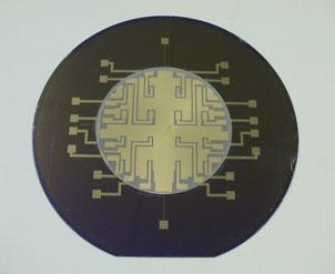
Ductile regime grinding is an important technology for the manufacture of many next generation components made from advanced materials. The application of MEMS (micro-fabricated electro-mechanical systems) technology to integrate a range of sensors, actuators and distributed electronics manufactured from difficult to process materials where properties and performance must be optimised is a major challenge. Precision machining processes have an important part to play in these developments. As an example one can consider the manufacture of a MEMS based boundary layer flow separation control system which has application on aircraft wings, helicopter rotors and fan or compressor blades. An integral part of such a system is shown in Figure 15.
|
|
|
Figure 15. MEMS based boundary layer flow separation control system (In collaboration with BAE Systems, Advanced Technology Centre, Sowerby,UK).
|
Figure 15 shows an example of how precision grinding processes can be integrated with micro-fabrication techniques. The photograph shows, from the base up, a 100mm diameter/400µm thick silicon wafer bonded to a 50 mm diameter/50 µm thick PZT wafer, 12 µm of titanium and a second 50 µm thick PZT wafer with associated electrodes.
The major challenges associated with the manufacture of this device have been to ensure damage free grinding of the silicon and PZT wafers and the attainment of the necessary parallelism. The overall flatness for the PZT layers is ±1µm, whilst surface finish is only required to be 20-30 nm Ra which is still good compared to most commercial ceramics. Achieving sub 100µm thick layers of PZT to this quality is not feasible by other means. The alternative method of lapping and polishing is very slow and expensive, whilst thick film deposition techniques do not produce material that has the necessary electro-active properties.
Summary
Diamond turning and diamond grinding processes can be used to generate high quality surfaces from brittle materials. By controlling the cutting forces or force per grit in the case of grinding, the extent of surface microfracture can be controlled.
The critical conditions for the on-set of damage can be estimated from existing models based on the hardness and fracture toughness characteristics of the workpiece. The range of machining parameters appropriate for ‘ductile regime’ machining can be predicted based on quasi-static indentation and ruling tests.
A key issue in developing successful damage free machining processes is the ability to maintain the cutting force below a critical value. This is often difficult, particularly over long cycle times, due to tool wear which tends to result in increased levels of force. A further problem when grinding with fine grit wheels is the tendency for wheel loading which further increases the cutting forces.
To address these problems ELID can be used to continually dress the grinding wheel so that stable and optimum grinding conditions can be maintained over extended cycle times.
References
1. P. N. Blake and R. O. Scattergood, “Ductile Regime Machining of Germanium and Silicon”, Journal Am. Ceram. Soc., 73 (1990) 949-957.
2. B. R. Lawn and D B Marshall. Hardness, “Toughness and Brittleness: An Indentation Analysis”, Journal Am. Ceram. Soc, 62 (1979) 347-349.
3. T. Bifano, T. Dow and R. O. Scattergood, “Ductile-regime grinding of brittle materials: Experimental results and the development of a model”, SPIE 966 (1988) 108-115.
4. Y. Tani, “Optimisation of Single Point Turning of Optical Glass”, SERC (UK) Report No. G/C 94544. (1987)
5. M. C. Gerchman and B. E. McLain, “Investigation of the Effects of Diamond Machining Germanium for Optical Applications”, SPIE, Vol. 929, (1988), 94-96
6. P A Beltrao, “Analysis of the potential for ductile mode machining of ferroelectric ceramic materials”, PhD thesis, Cranfield University, (1998).
7. Shore, P., “Machining of optical surfaces in brittle materials using an ultra-precision machine tool”, PhD thesis, Cranfield University, (1995).
8. Y. Namba, et al., “Ultra-Precision Surface Grinder having a Glass Ceramic Spindle of Zero-Thermal Expansion”, Annals of CIRP, 38/1 (1983).
9. D. J. Stephenson, D. Veselovac, S. Manley and J. Corbett, “Ultra precision grinding of hard steels”, Precision Engineering 25 (2001) 336-345
10. D. J. Stephenson, J Hedge and J. Corbett, “Surface finishing of Ni-Cr-B-Si composite coatings by precision grinding”, Int. Journal of Machine Tools and Manufacture, 42 (2002) 357-363.
11. D. J. Stephenson, J. Corbett and J Hedge, “Ultra precision grinding using the Tetraform concept”, Abrasives Magazine, Feb/March, (2002) 12-16
12. M. C. Shaw, “Principles of abrasive processing”, Oxford University Press, UK, (1996)
13. H. Ohmori, “Electrolytic In-Process Dressing Grinding Technique for Ultra Precision Mirror Surface Machining”, JSPE, 26 [4] (1992).
14. H.Ohmori and T. Nakagawa, “Utilisation of non linear conditions in precision grinding with ELID for fabrication of hard material components”, Annals of the CIRP, 46 [1] (1997) 261-264.
15. A. Buttner, “Electrolytic Dressing of Diamond Wheels for use in Steel Grinding”, IDR, Nov. (1969), 205-208.
Contact Details
|