Introduction Ti-29Nb-13Ta-4.6Zr (TNTZ) is a low-modulus titanium alloy developed by the authors for biomedical applications [1]. TNTZ demonstrates much greater biological and mechanical biocompatibility when compared with conventional Ti-6Al-4V ELI used for biomedical applications. Titanium alloys, even TNTZ, are not bioactive. In order to improve the biocompatibility of titanium alloys, in general, a hybridization with bioactive ceramics such as hydroxyapatite (HAP) is performed. There are various types of HAP modification processes, for example, plasma-spray coating, alkali treatment, electrochemical treatment, and dip-coating process [2]. Among these processes, the alkali treatment process [3] or the electrochemical treatment process [4] is advantageous for TNTZ because the substrate does not require to be heated at high temperatures, which results in the microstructure change and degradation in the mechanical properties. The proper condition of the electrochemical treatment process to form HAP on TNTZ is unknown. The electrochemical treatment processes, where the conditions were variously changed, were performed with TNTZ. The proper condition of the electrochemical treatment process to form HAP on TNTZ was investigated in this study. Experimental Procedure Round bars of TNTZ with a diameter of 10 mm and grade 2 pure titanium (CP-Ti) were used in this study. The TNTZ bar was solution treated at 1063 K for 3.6 ks followed by water quenching. The CP-Ti bar was annealed by heating it at 1023 K for 3.6 ks and followed by air-cooling. Disc specimens with a thickness of 2.0 mm to be used for the electrochemical treatment were machined from the heat-treated bars. A copper wire was bonded to one side of the disc specimen using an electro-conductive silver paste that could be hardened, and the other side of the disc specimen was covered with an epoxy resin, except the test area. The test area was wet-polished by using waterproof abrasive papers up to # 600 and then subjected to ultrasonic cleaning in methanol followed by drying in air. The disc specimens embedded in epoxy resin were subjected to an electrochemical treatment in which an anodic treatment was followed by a cathodic treatment in an electrolyte of 0.1 kmol/m3 calcium nitrate (Ca(NO3)2) solution. CP-Ti or TNTZ acted as the action electrode and Pt was the counter electrode. The anodic treatment was performed at 7.5 V for 3.6 ks. The cathodic treatment was performed after the anodic treatment in order to form calcium hydroxide, which acts as precursor to induce the formation of HAP; it was carried out at –1.0 V, –2.0 V and –3.0 V for 0.9 ks. The disc specimens embedded in epoxy resin subjected to electrochemical treatment were cleaned using distilled water, and they were then separated from the epoxy resin. After removal from the epoxy resin, the disc specimens were dipped into a simulated body fluid: SBF (Na+: 142.0, K+: 5.0, Mg2+: 1.5, Ca2+: 2.5, Cl–: 148.8, HCO3–: 4.2, HPO4–; 1.0, SO42–: 0.5, mol/m3), which was developed by Kokubo et al. [3] and referred to as the named as Kokubo solution they were also individually dipped into 1.5SBF, whose concentration was 1.5 times that of the SBF. Here, the pH and temperature of SBF and 1.5SBF were buffered at 7.4 with tris–(hydroxymethyl) aminomethane ((CH2OH)3CNH3 and hydrochloric acid at 310 K. The dipping times in SBF were 21.6, 43.2, 86.4, 259.2, and 1209.6 ks. The dipping times in 1.5SBF were 21.6, 43.2, 86.4, and 259.2 ks. After dipping, the specimens were dried in air at 313 K for 3.6 ks. The flowchart, specimen preparation and equipment of the abovementioned electrochemical treatment process are schematically shown in Figure 1. 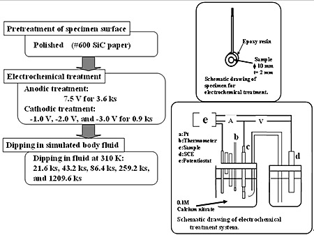
Figure 1. Schematic drawing of electrochemical treatment process. The surfaces of the specimens after the electrochemical treatment and the dipping treatment were analyzed using a thin film X–ray diffractometer (XRD), scanning electron microscopy (SEM), energy dispersion spectroscopy (EDS) and Auger electron spectroscopy (AES) with sputtering to determine the depth profile of each element. Results and Discussion Specimen Surface Change after Electrochemical Treatment The oxygen content detected by EDS and AES at the surface of the CP-Ti specimen after the anodic treatment was greater than that of TNTZ. The oxygen contents before and after anodic treatment for CP-Ti were 10.6 % and 26.4 %, respectively, while they were 13.0 % and 22.0 % for TNTZ. Therefore, the oxygen (O) diffused into the CP-Ti and TNTZ specimen, and formed oxides on the surface of the specimens. EDS analysis led to the results that TiO2 was mainly formed on the surface of the CP-Ti specimen, and TiO2, Nb2O2, Ta2O3, and ZrO2 were mainly formed on the surface of the TNTZ specimen. There is a possibility for complex oxides to form, in particular, on the surface of the TNTZ specimen. Further investigation is needed to determine which complex oxides are formed. The profiles of the distributions of each element near the surfaces of the CP-Ti and TNTZ specimens before and after the anodic treatment evaluated using an AES are shown in Figures 2 and 3, respectively where the sputtering depth was evaluated using a sputtering rate of 30 nm/min for SiO2. Before and after the anodic treatment, the thicknesses of the oxide layer formed on the surface of the CP-Ti specimen are around 5 nm and 50 nm, respectively whereas those formed on the TNTZ specimen are around 5 nm and 70 nm, respectively. (a) Before Anodic Oxidation 
(b) After Anodic Oxidation Figure 2. AES results of CP-Ti surfaces (a) before and (b) after anodic oxidation treatment. (a) Before Anodic Oxidation 
(b) After Anodic Oxidation Figure 3. AES results of AES of TNTZ surfaces (a) before and (b) after anodic oxidation treatment. Specimen Surface Change after Cathodic Treatment Polygon-shaped crystals of calcium hydroxide were densely formed on the entire surface of the CP-Ti and TNTZ specimens after each cathodic treatment. The thickness of the calcium hydroxide layer formed on the surfaces of the CP-Ti and TNTZ specimens subjected to the cathodic treatment at, for example, –2.0 V were 20 μm and 15 μm, respectively. Therefore, the calcium hydroxide layer is thicker on the CP-Ti specimen than the TNTZ specimen. Specimen Surface Change after Dipping in SBF Continuous spherical products were partially formed on the surface of CP-Ti and TNTZ specimens by dipping in SBF for 21.6 ks and 86.4 ks, respectively. Further, these spherical products were homogeneously formed on the entire surface of the CP-Ti specimen by dipping for 604.8 ks; however, they were still partially formed on the surface of the TNTZ specimen by dipping for 604.8 ks. The spherical products formed on the entire surface of the TNTZ specimen by dipping in SBF for a period extending over 1209.6 ks. Figures 4 and 5 show the XRD profiles of the surfaces of the CP-Ti and TNTZ specimens dipped in SBF at various times after the electrochemical treatment. The peaks of HAP can be observed on the surface of the specimens at a dipping time of over 259.2 ks for CP-Ti and 604.8 ks for TNTZ in addition to the peaks of the matrix. The peaks of HAP become more visible as the dipping time increases. The spherical products formed on the surface of the CP-Ti and TNTZ specimens after the abovementioned dipping in the SBF are in fact HAP. It is possible to form HAP on the entire surface of the TNTZ specimen by dipping for a period extending over 1209.6 ks in the SBF after the electrochemical treatment. The electrochemical treatment process is applicable for modification of the TNTZ surface to form HAP. In the case of the electrochemical treatment process, the formability of HAP on the surface of the TNTZ specimen is less than that on the surface of the CP-Ti specimen. 
Figure 4. XRD profiles of CP-Ti specimens dipped in SBF for (a) 21.6 ks, (b) 43.2 ks, (c) 86.4 ks, (d) 259.2 ks, (e) 604.8 ks and (f) 209.6 ks. 
Figure 5. XRD profiles of TNTZ specimens dipped in SBF for (a) 21.6 ks, (b) 43.2 ks, (c) 86.4 ks, (d) 259.2 ks, (e) 604.8 ks and (f) 1209.6 ks. Formability of HAP and Amount of Calcium Hydroxide Formed The state of formation of HAP in the SBF by the electrochemical treatment process is considered to depend on the amount of calcium hydroxide formed on the surface of the specimen during the cathodic treatment stage. As mentioned above, the thickness of the calcium hydroxide layer formed on the TNTZ specimen was, in fact, less than that on the CP-Ti specimen by the cathodic treatment at –2.0 V for 0.9 ks, and the formability of HAP on the TNTZ specimen was less than that on the CP-Ti specimen. The formability of HAP on the TNTZ specimen was investigated since varying the potential applied for the cathodic treatment differently modified the thickness of the calcium hydroxide layer formed on the surface of the TNTZ specimen. In this case, 1.5SBF solution was used in order to quantitatively investigate the formability of HAP in a relatively short period. Figure 6 shows the SEM micrographs of the cross sections near the surfaces of the CP-Ti and TNTZ specimens after cathodic treatments at –1.0 V, –2.0 V, and –3.0 V for 0.9 ks. The thicknesses of the calcium hydroxide layer formed on the surface of CP-Ti specimen at –1.0 V, –2.0 V, and –3.0 V were around 5.5 μm, 20 μm, and 40 μm, respectively, whereas those on the surface of the TNTZ specimen were 3.8 μm, 15 μm, and 20 μm, respectively. The thickness of the calcium hydroxide layer increases with decreasing the applied potential in the cathodic treatment. 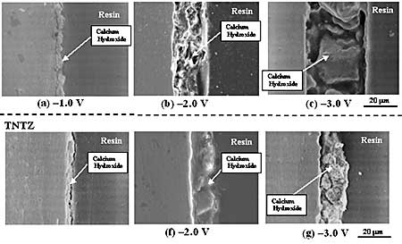
Figure 6. SEM micrographs of cross sections near the specimen of the CP-Ti and TNTZ Specimens after cathodic treatments at (a) and (e) –1.0 V, (b) and (f) –2.0 V, and (c) and (g) –3.0 V for 0.9 ks. Figure 7 shows SEM micrographs on the surfaces of CP-Ti and TNTZ specimens after dipped in 1.5 SBF for 21.6 ks, 43.2 ks, 86.4 ks, and 259.2 ks after cathodic treatment at -2.0 V for 0.9 ks as the representative result. The surface of the CP-Ti is partially covered by HAP for dipping times below 43.2 ks, while the entire surface of the CP-Ti is covered by HAP dipping times above 86.4 ks. The surface of the TNTZ specimen is partially covered by HAP dipping times below 86.4 ks, while the entire surface of the TNTZ specimen is covered by HAP for dipping times above 259.2 ks. The surface uncovered by HAP is considered to be the bare surface of the specimen from the X-ray profiles shown in Figures 4 and 5. 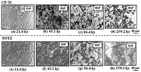
Figure 7. SEM micrographs on the surfaces of the CP-Ti and TNTZ specimens after dipped in 1.5 SBF for (a) and (e) 21.6 ks, (b) and (f) 43.2 ks, (c) and (g) 86.4 ks, and (d) and (h) 259.2 ks after cathodic treatment at -2.0 V for 0.9 ks. The area fractions of HAP formed on the surfaces of the CP-Ti and TNTZ specimens dipped in 1.5 SBF are tabulated in Table 1 with various times after the cathodic treatments at various applied potentials. The area fractions of HAP formed on the surfaces of the CP-Ti and TNTZ specimens are the largest when the cathodic treatment is performed at –2.0 V. At this cathodic potential, the process times required for HAP to cover the entire surfaces are 86.4 ks for the CP-Ti specimen and 259.2 ks for the TNTZ specimen. Comparing the results obtained in the case of SBF mentioned in the section 3.3, the formability of HAP is higher in 1.5SBF than in SBF. The area fractions for the cathodic treatment at –3.0 V are a little smaller than that for the cathodic treatment at –2.0 V, except for a dipping time of 259.2 ks. The thickness of the calcium hydroxide layer formed at a potential of –3.0 V was greater than that formed at a potential of –2.0 V as stated above. Therefore, the additional time required for the calcium hydride layer formed at a potential of –3.0 V layer to be dissolved into the SBF. This leads to a little smaller area fraction of HAP at a potential of –3.0 V compared to the area fraction of HAP at a potential of –2.0 V. Therefore, the most effective cathodic treatment potential to form HAP on the entire surfaces of the CP-Ti and TNTZ specimens is –2.0 V. The thicknesses of HAP formed on the surface of the CP-Ti and TNTZ specimens dipped into 1.5SBF for 259.2 ks after the cathodic treatment at –2.0 V for 0.9 ks were around 14 μm and 9.5 μm, respectively. The thickness of the calcium hydroxide layer formed on the surface of the TNTZ specimen is a little less than that of the CP-Ti specimen. The thickness of the calcium hydroxide layer formed on the surface of the TNTZ specimen subjected to the cathodic treatment at –3.0 V followed by dipping into 1.5SBF for 259.2 ks was around 20 μm. By the cathodic treatment at –3.0 V, the thickness of the calcium hydroxide layer formed on the surface of the TNTZ specimen can be controlled to be the same as that formed on the surface of the CP-Ti specimen by the cathodic treatment at –2.0 V. Even for the same thickness of the calcium hydroxide layer, the TNTZ specimen has an inferior formability of HAP to the CP-Ti one. This inferior formability of the TNTZ specimen does not depend on the thickness of the calcium hydroxide layer. The deposition mechanism of HAP for pure titanium proposed [4] is schematically shown in Figures 8 and 9. This process is applicable to the CP-Ti in this study. The formation of the TiO2 oxide is considered to be one of the key points for forming the HAP. For the TNTZ specimen, other oxides such as Nb2O2, Ta2O3, and ZrO2 are formed in addition to TiO2. These oxides may be more stable compared to TiO2. Finally, the amount of the hydroxyl group may be less for the TNTZ specimen compared to the CP-Ti. However, the clear mechanism for the inferiority of the formation of HAP in the TNTZ specimen to that in the CP-Ti cannot be mentioned in the present state. It may be due to the nature of the specimen surface, oxide layer formed on the specimen, or the amount of the hydroxyl group. Further investigations are required in order to clarify this issue. 
Figure 8. Schematic drawing of formation of calcium hydroxide layer by electrochemical treatment. 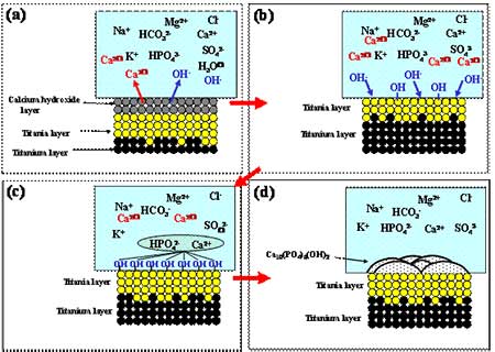
Figure 9. Schematic drawing of apatite formation in SBF solution. Table 1. Area fractions of HAP on the surfaces of the CP-Ti and TNTZ specimens (%). | | | CP-Ti | 21.6 | 14.1 | 19.9 | 11.2 | | 43.2 | 34.4 | 93.0 | 78.7 | | 86.4 | 70.9 | 100 | 94.3 | | 259.2 | 100 | 100 | 100 | | TNTZ | 21.6 | 0.0 | 0.0 | 0.0 | | 43.2 | 8.2 | 32.4 | 17.4 | | 86.4 | 31.3 | 71.5 | 63.5 | | 259.2 | 69.9 | 100 | 100 | Conclusions An electrochemical treatment that comprises anodic oxidation and cathodic polarization was performed on Ti-29Nb-13Ta-4.6Zr (TNTZ) and pure titanium (CP-Ti) under various conditions in a calcium nitrate solution. The treated alloy and pure titanium were then dipped into a simulated body fluid (SBF) and 1.5SBF, where the concentrations of the constituents were 1.5 times that of SBF. The characterization and morphology of the HAP formed on the alloy were examined by comparing with those of CP-Ti. The following results were obtained. (1) The electrochemical treatment process is effective in forming HAP in SBF on the surface of TNTZ; however, the formability of HAP on TNTZ is inferior to that on CP-Ti. (2) The formability of HAP on the surfaces of CP-Ti and TNTZ is higher in 1.5SBF than in SBF. Acknowledgements The authors wish to thank NSERC, Canada for financial support for this work. References 1. M. Niinomi, T. Hattori, K. Morikawa, T. Kasuga, A. Suzuki, H. Fukui and S. Niwa, “Development of Low Rigidity β-type Titanium Alloy for Biomedical Applications”, Mater. Trans., 43, 12 (2002) 2970-2877. 2. M. Niinomi, “Recent Research and Development in Titanium Alloys for Biomedical Applications and Healthcare Goods”, STAM, 4 (2003), 445-454. 3. H. M. Kim, F. Miyaji and T. Kokubo, “Effect of heat treatment on apatite-forming ability of Ti metal induced by alkali treatment”, J. Mater. Sci.: Mater. in Medicine, 8 (1997), 341-347. 4. A. Osaka, X. X. Wang, S. Hayakawa and K. Tsuru, “Biomimetic Deposition of Apatite on Electrochemically Oxidized Titanium Substrates”, Bioceramics, 13 (2000), 263-266. Contact Details |