DOI :
10.2240/azojomo0322
Michelina Catauro, Flavia Bollino, Ishu Kansal, Elie Kamseu, Isabella Lancellotti, Cristina Leonelli
Copyright AZoM.com Pty Ltd.
This is an AZo Open Access Rewards System (AZo-OARS) article distributed under the terms of the AZo–OARS https://www.azom.com/oars.asp which permits unrestricted use provided the original work is properly cited but is limited to non-commercial distribution and reproduction.
Submitted: 28 March, 2011
Posted: 19 May, 2012
Topics Covered
Abstract
Keywords
Introduction
Methods and Materials
Geopolymer Preparation
Geopolymer Characterization
Bioactivity Tests
Results and Discussion
Sodium Based Geopolymers
Potassium Based Geopolymers
Conclusions
References
Contact Details
Abstract
In this study three different geopolymer compositions have been investigated and characterized as potential biomaterials. The first two geopolymer formulations are mainly composed of metakaolin, with some silica additions in order to achieve a Si/Al molar of 2.10 while the third one contains a reduced amount of metakaolin and comprises mainly of silica gel with composition: H24AlK7Si31O79 with Si/Al = 31. Further, NaOH pellets and sodium silicate (Na2SiO3) were added in the first two formulations in different concentrations as activator and ligand, respectively, while KOH additions were made to the third geopolymer formulation (separately or jointly with potassium silicate solution). Room temperature consolidation was followed by thermal activation of composition with Si/Al=31 at 60 °C for 150 min and at 500 °C for 180 min. The work presents exhaustive microstructural characterization (infrared spectroscopy, electron microscopy and X-ray diffraction) of as synthesized geopolymer samples in conjunction with their mechanical and in vitro bioactivity evaluation. The materials were composed of amorphous aluminosilicates with a limited amount of zeolitic phases, found on the top surface. The compressive strength of the first two compositions was higher than 15 MPa and flexural strength around 2 MPa after 2 days of curing at room temperature. Compressive strength tests were carried out on composition with on Si/Al = 31 geopolymer on both activated sample series and demonstrated that when added separately the activator leads to more fragile specimens (0.90 MPa vs. 1.95 MPa). To the best of authors’ knowledge the effect of geopolymer preparation on mechanical properties of thermally activated Si/Al = 31 formulation has never been proved before. The bioactivity was successfully tested with the soaking of the samples in a simulated body fluid (SBF) for 3 weeks. The formation of a layer of hydroxyapatite on the surface of the materials was shown both by SEM micrograph and EDS analysis.
Keywords
Geopolymers, FTIR, Bioactivity, Compressive Strength, Molar Ratio Si/Al = 31
Introduction
In the biomaterials field, some systems based on amorphous silicate network like bioactive glasses1, calcium phosphates2,3, aragonite4, are successfully applied in bone surgery. As a matter of fact numerous synthetic aluminosilicates5,6, possess chemical properties which offer employment as bone graft biomaterials. Among these aluminosilicates also geopolymers can be listed. They can be defined as cementitious materials that are formed by mixing aluminosilicate powders (e.g., metakaolin) with alkali or alkali-silicate solution7-10.
The formation of [Mz(AlO2)x(SiO2)y.MOH.H2O] gel, which essentially relies on the dissolution of aluminosilicates materials, is a dominant step in geopolymerisation. When the gel phase hardens, the separate aluminosilicate particles are bound together with the gel which acts as binder11. Authors12,13 have described the reaction process of the gel formation indicating that Al-Si solid particles in alkaline solution conduct to the formation of monomers -OSi(OH)3 and Al(OH)4-. The successive reactions between these monomers, alkali ions and water results in the formation of dimer and longer chains14. The final geopolymers are then formed with tightly packed 3D semi-crystalline microstructure with good mechanical properties15,16. Typically, better strength behaviour is obtained for mixtures with Si/Al molar ratio in the range of 1.65-2.10 combined with Na/Al ratio near 1. Increased silica content usually reduces the mechanical strength while multiple alkali sources, KOH and NaOH, can act in a synergistic way to promote samples of optimal chemical and mechanical characteristics13,14,17. The compressive strength of geopolymer materials depends on a number of factors including gel phase strength, the ratio of gel phase/undissolved Al-Si particles size, the distribution and the hardness of the undissolved Al-Si particles, the amorphous nature of geopolymers or the degree of crystallinity as well as the surface reaction between the gel phase and the undissolved Al-Si particles.
High mechanical strength of geopolymers results on the rapid solidification within hours and rapid early strength development, as it is already known for phosphatic dental cements18. In addition a good level of porosity can be easily introduced at room temperature by adding specific additives19. Both these characteristic make these materials attractive for hard tissue prostheses or bone fillers and bindings.
Even though these types of materials are particularly interesting for their fast strength development, their bioactivity or at least biocompatibility has not yet been investigated extensively. The aim of the present paper is to investigate the application of metakaolin based geopolymers as potential biomaterials as well as studying the effect of sample preparation on silica rich metakaolin geopolymer already proposed in literature as bony filling6. The preparation and characterization of a total of three different formulations are reported.
Methods and Materials
Geopolymers Preparation
Metakaolin (MK) was used as the principal source of aluminosilicate. The choice was based on the fact that it improves mechanical strength and reduces the transport of water and salts in the final product. Metakaolin, with a molar ratio Si/Al = 2.10, was prepared by calcining kaolinitic clay at 700 °C in muffle oven for 2 hrs.
Two different formulations of geopolymer materials, containing different amount of NaOH and with two different Na/Al ratios, were prepared as shown in Table 1.
Laboratory grade NaOH pellets and distilled water were used to prepare 8M alkaline solution. Sodium silicate solution (grade N, RM3, 0 from Ingessil s.r.l., Verona, Italy) with a mol/mol ratio of SiO2/Na2O equal to 2.99 was used.
Designated quantities of sodium hydroxide and silicate solutions were mixed with 100 g batches of metakaolin (solid/liquid ratio of 1.66). No additional water was added apart from that of NaOH and Na-silicate20. Overall porosity, 60vol%, is visible in Figure 1a.
Table 1. Formulation of the two geopolymers, with Si/Al = 2.10, prepared for this study (Na silicate solution used: 30 ml per 100 g MK)
| Composition |
NaOH 8M Solution |
Na/Al |
Curing time (days) |
| GP120 |
20 ml/100g MK |
0.77 |
15 |
| BGP130 |
30 ml/100g MK |
1.05 |
30 |
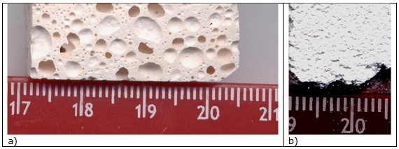
Figure 1. Optical micrograph of (a) GP120 (BGP130 has similar microstructure) and (b) BGP3 P (BGP3 S has similar microstructure) bulk samples.
The resulting slurries were stirred mechanically for about 10 min to reach good homogenization, and then poured in a closed polyethylene mould for 12 hrs at room temperature before demoulding. The curing time was 30 days for both the compositions.
In order to reduce the impact of non-bonded Al atoms in the final product, an increase of silica was operated by SiO2 additions to MK. Thus the percentage of Al present in the final formulation decreased to Si/Al =31, but, at the same time, the effect of 3D bonded silica chains increased the network connectivity, decreasing Al release4-6.
Table 2. Silica rich formulation and details of activation: P refers to sample prepared using pellets of KOH directly added to K- silicate (water added =35ml). S refers to sample prepared using 8M KOH solution (water added =25ml).
| SAMPLE |
Activ. |
Label |
Consolidation |
Thermal treatment |
| B-GP1 |
P |
B-GP1P |
3 or 4 days in a closed plastic bag |
none |
| |
S |
B-GP1S |
3 or 4 days in a closed plastic bag |
none |
| B-GP 2 |
P |
B-GP2P |
1 day in Teflon® container prior thermal treatment |
60°C in Teflon® for 150 min |
| |
S |
B-GP2S |
1 day in Teflon® container prior thermal treatment |
60°C in Teflon® for 150 min |
| B-GP 3 |
P |
B-GP3P |
treated after one week from preparation |
Same as B-GP 2 plus 500°C for 180 min |
| |
S |
B-GP3S |
treated after one week from preparation |
Same as B-GP 2 plus 500°C for 180 min |
Following literature formulation of Oudadesse et al.4-6 a third geopolymer sample is here proposed with theoretical formula: H24AlK7Si31O79. The raw materials used were KOH, K2SiO3 and SiO2 apart from the previously mentioned metakaolin. Laboratory grade KOH pellets and distilled water were used to prepare 8M alkaline solution (4.45 g of solution in 1.225 g of MK) or were directly added to the potassium silicate solution (1.995 g in 7.164 mol). Potassium silicate solution (grade N, RM3, 0 from Ingessil s.r.l., Verona, Italy) with a mol/mol ratio of SiO2/K2O equal to 3.10 was used. In both procedures, 1.225 g MK was added with 14.655 g of SiO2 and consolidation was performed as reported in Table 2. The SiO2 added was completely amorphous in nature which was produced hydrothermally from natural silicates21.
Thermal cycles for consolidation the 3D silica network were applied, as reported in Table 2, following literature indications4-6. Microstructure of BGP3 P sample is visible in Figure 1b.
Geopolymer Characterization
The final geopolymers were tested for crystalline phases evolution with X-Ray diffraction (XRD) on both surface and bulk of each sample (Philips Electronic Instruments, model PW 1730).
The compressive strength was determined by using mechanical testing machine Instron, USA. The end surfaces of specimens and surface were polished flat and parallel to avoid the requirement for capping. The cylinders (2 cm diameter x 4 cm thickness) were centred in the compression-testing machine and loaded to complete failure. The compressive strength was calculated by dividing the maximum load (N) at failure by the average cross-sectional area (m2). The final result is the average value of three tested specimens.
Fourier transform infrared (FTIR) transmittance spectra were recorded in the 400-4000 cm-1 region using a Prestige 21 Shimatzu system, equipped with a DTGS KBr (Deuterated Tryglycine Sulphate with potassium bromide windows) detector, with resolution of 2 cm-1 (45 scans). KBr pelletised disks containing 2 mg of sample and 200 mg KBr were prepared. FTIR spectra were elaborated by Prestige software (IRsolution).
Bioactivity Tests
In order to study their bioactivity, one disc per each composition was soaked in a simulated body fluid (SBF) solution with ions concentration nearly equal to those in human blood plasma (Table 3), at 37 °C and in a polystyrene bottle, as scheduled by bioactivity test in vitro22. The SBF solution was prepared by dissolving reagent grade chemicals NaCl, NaHCO3, KCl, MgCl2•6H2O, CaCl2, Na2HPO4, Na2SO4 (Sigma-Aldrich) in ultra-pure water and buffered at pH 7.4 using HEPES sodium salt (C8H18N2O4SNa) (Sigma-Aldrich) and 1M NaOH.
Table 3. Simulated body fluid (SBF) ionic concentration (mM).
| |
Na+ |
K+ |
Mg2+ |
Ca2+ |
Cl- |
HCO3- |
HPO42- |
SO42- |
| Human blood plasma |
142.0 |
5.0 |
1.5 |
2.5 |
103.0 |
27.0 |
1.0 |
0.5 |
| SBF |
142.0 |
5.0 |
1.5 |
2.5 |
148.0 |
4.2 |
1.0 |
0.5 |
In these tests the ratio between the total surface (ST) of the material in contact with the SBF solution and the volume of such solution (VSBF) influence the reaction of formation of a hydroxyapatite layer. A constant ratio of ST/VSBF =10 mm2/ml was used.
After an immersion periods of 21 days, the materials were removed from the SBF, gently washed with ultra-pure water, and dried at 40 °C. The ability to form an apatite layer was studied by Environmental Scanning Electron Microscopy (ESEM QUANTA 200) observations coupled with energy dispersion spectroscopy- EDS (X-EDS Oxford INCA-350) analyses.
Results and Discussion
Sodium Based Geopolymers
Sodium based geopolymer composition proposed here are capable of offering a controlled porous material when appropriately added with a poring agent as reported in literature19. Final bulk density value was about 1.56-1.55 g/cm3 with a porosity of 38 ± 5.1 vol. %; compressive strength 15.0 ± 4.4 MPa, bi-axial flexural strength 8.0 ± 4.5 MPa. Since the mechanical characterization has been reported elsewhere19,23, in this contribution we are focused only on their application as biomaterials. With this in mind we started with a complete microstructural characterization of the two formulations GP120 and BGP130.
The two geopolymer formulations were analysed by XRD on both the surface and bulk in order to evaluate material’s structure uniformity and the nature of the geopolymeric gel. The bulk of both samples show traces of the kaolinitic clay which is, not fully transformed into metakaolin, as it always happen in industrial processes. XRD pattern of GP120 (Figure 2) is reported as an example since for BGP130 the same crystalline phases were identified. The geopolymer appears largely amorphous with traces of crystalline phases. In particular the following phases were identified: monoclinic kaolin Al2Si2O5(OH)4 (JCPDF file 05-0221), monoclinic nacrite 2M Al2Si2O5(OH) 4 (JCPDF file 16-0606), which is a phyllosilicate clay mineral polymorph of kaolinite, along with traces of another phyllosilicate with monovalent cation and possibly muscovite 1M-like structure, KAl2Si3AlO10(OH)2 (JCPDF file 07-0025). Furthermore, as a consequence of the reaction between metakaolin and the alkaline solutions, Na-aluminosilicates were developed, such as Na4Al2Si2O9 (JCPDF file 10-0031) and Na6Al4Si4O17 (JCPDF file 10- 0033). During geopolymerization the dissolution and nucleation of gel are generally exothermic reactions so the energy of gel growth to polysialates is not enough to conduct to crystalline phases. Therefore a significant broad band due to the amorphous nature of the geopolimeric gel is also evident in all the XRD patterns for both the compositions.
Kaolinite and nacrite were observed on the surface probably as traces of the unreacted kaolinitic clay used in the synthetic process along with Na- aluminosilicate Na2Al2SiO6 (JCPDF file 30-1148) due to the reaction with the alkaline solution (Figure 3). In addition, a carbonate phase, possibly trona Na3H(CO3)2.2H2O (JCPDF file 29-1447) was also evident, due to the reaction with the atmosphere.
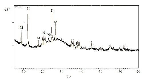
Figure 2. XRD pattern of GP120 bulk sample (K = kaolinite, N = nacrite, M = muscovite, Na = Na-aluminosilicates)
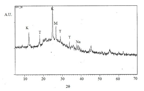
Figure 3. XRD pattern of GP120 sample surface (T = trona, K = kaolinite, N = nacrite, M = muscovite, Na = Na2Al2SiO6)
In the geopolymers FTIR spectra, an approximate relationship between the frequency of the absorption bands and the ratio of Si:Al in the aluminosilicate framework was observed by Milkey24: the higher the Al inclusions, the lower the wavelength. In Figures 4 and 5 the spectra of samples GP120 and BGP130, respectively, inner and surface parts are shown. All the spectra present the strongest vibration typical of all aluminosilicates (see Table 3), which are assigned to internal vibrations of Si-O-Si and Si-O-Al. In addition other common feature are present: two absorption bands at about 3450 and 1650 cm-1 resulting from hydration water, a strong Si-O stretching vibration at about 1080-1100 cm-1 and Si-O bending vibration at about 450-470 cm-1. Moreover, the bands between 600-800 cm-1 are due to Al-O-Si vibrations25,26 : in particular, the bands at 798 cm-1 are due to Al-O stretching vibrations. The surface spectra (Figures 4B and 5B) show Al-OH stretching vibrations at 914-916 cm-1 while Si-OH bending vibrations, at 850 cm-1, are present only in BGP130 surface spectrum (Figure 5a). The presence of a band at 1460 cm- 1 in Figure 4b and 5b indicates that sodium carbonate species are present on the surface of this sample confirming the XRD results which shows the reactivity of the surface with the atmosphere. The absence of this band in Figure 4a and 5a indicates that sodium carbonate species are not present in the samples inner part27.
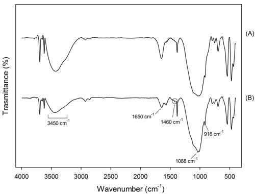
Figure 4. FTIR of sample GP120 (a) inner and (b) surface part
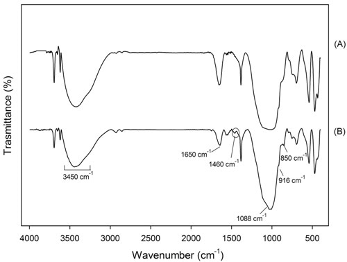
Figure 5. FTIR of sample BGP130 (a) inner and (b) surface part.
Table 4. IR characteristic bands and their interpretation
| Absorption Bands |
Interpretation |
| 3450 and 1650 cm-1 |
hydration water |
| 1080-1100 cm-1 |
Si-O stretching vibration |
| 450-470 cm-1 |
Si-O bending vibration |
| 840 cm-1 |
Si-OH bending vibration |
| 798 cm-1 |
Al-O stretching vibration |
| 914-916 cm-1 |
Al-OH stretching vibration |
| 600-800 cm-1 |
Al-O-Si vibrations |
| 1460 cm-1 |
Na2CO3 |
The microstructural characterization has been conducted by scanning electron microscopy (ESEM/EDS) in order to compare the two geopolymer formulations and their different behaviour (Figure 6). Both the samples do not show porosity in the micrometric range. The overall porosity19 has been measured with Archimede’s method. The absence of pores of micrometric size, confirmed by ESEM micrographs, is due to a well designed formulation. In addition the good mechanical properties are justified by the nanometric size of pores. These pores, generally called gel pores (< 15 nm) are too small to affect the mechanical properties28.
GP120 shows a homogeneous microstructure with some incompletely dissolved grains embedded in a compact geopolymeric gel. EDS analysis of grains revealed that they contain alumina and silica in an atomic ratio near to 1 suggesting that they are metakaolin particles. On the other hands, BGP130 composition shows a two-phase microstructure characterized by two geopolymeric gels with different Na content. The grainy one contains higher amount of Na (average Na/Al = 0.64) with respect to the smooth one (average Na/Al = 0.53) (Figure 6b and 6c). In addition, a particle rich in potassium is also evident which can be attributed to muscovite, clayey crystalline phase identify by XRD. Both the geopolymers exhibit good mechanical properties; therefore the sample integrity is not degraded by the presence of granular inclusions.
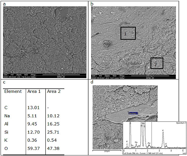
Figure 6. ESEM micrographs of (a) GP120, (b) and (d) BGP130. (c) reports EDS data collected in area 1 and 2 of image in (b).
Moreover an evaluation of the morphology of the apatite deposition, after bioactivity tests, and a qualitative elemental analysis were also carried out by SEM accompanied by EDS as reported in Figure 7, which shows ESEM micrographs of GP120 soaked in SBF for 21 days. The layer of apatite is not visible on sample surface, proving that this particular formulation is not bioactive. BGP130, on the contrary, is bioactive: in fact the characteristic apatite globular crystals are clearly visible29, as shown in Figures 7,b and c. These studies were considered sufficient to identify the presence of apatite on the geopolymer surface; additional XRD investigations were not possible due to the extremely low amount of the newly formed crystalline phase.
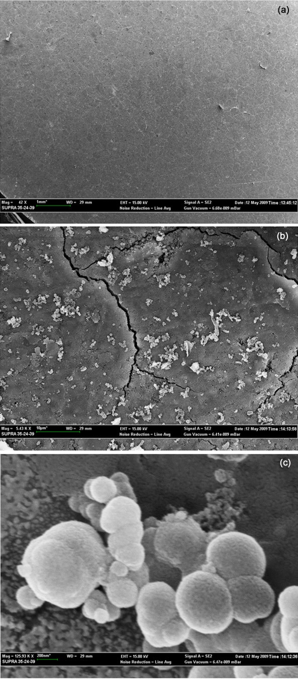
Figure 7. ESEM micrograph of (a) GP120 and (b) BGP130 after soak in SBF for 21 days. (c) enlargement of (b).
A possible explanation for this different bioactive behaviour is the presence of a greater number of –Si–ONa and –Al–ONa groups on the surface of BGP130 (Na/Al = 1.05) when compared to GP120 (Na/Al = 0.77). As reported in the literature30,31 when exposed to SBF, sodium silicate glasses and ceramics released Na+ ions via exchange with H3O+ ions in SBF to form Si–OH and Al–OH groups on their surface; this reaction causes a pH increase of SBF solution and, consequently, Si-OH and Al-OH groups are dissociated into negatively charged units Si–O-. These groups combine with Ca2+ ions present in the fluid imposing an increase of positive charge on the surface. In addition Ca2+ ions combine with the negative charge of the phosphate ions to form amorphous phosphate, which spontaneously transforms into hydroxyl-apatite [Ca10(PO4)6 (OH)2] where the atomic ratio Ca/P is 1.6032. The EDS analysis confirms that the surface layer observed in the SEM micrographs consists of calcium phosphate showing contents of Ca:P (atomic %) 3.14:1.95 for a value of Ca/P=1.61. Before biomedical applications of this porous metakaolin based geopolymer the issue of the potential problems caused by the alkalinity as well as the possible leaching of Al into the SBF should be addressed. As reported in literature, the highly alkaline nature of the material can induce cell death, and the effect of aluminium leached from the implant in living organisms is controversial; some authors33-35 report that low aluminium concentrations lead to brain disease, although lower concentrations of aluminium may be beneficial and stimulate the proliferation of osteoblasts and new bone formation31. However, with various approaches it is possible to obtain stable geopolymers both in vitro and in vivo5,36.
Potassium Based Geopolymers
Potassium based geopolymers have already been tested in vitro and in vivo4-6 and they show high bioactivity/compatibility. Oudanesse et al.5 demostrated that amorphus geopolymers of the potassium-poly(sialate)-nanopolymer type, obtained with molar ratios Si:Al = 31, K2O:SiO2= 0.54 and thermally-treated at 500 °C, give excellent results in terms of biological compatibility. This geopolymer matrix was able to reduce alkalinity and the amount of free aluminium and to provide high porosity for biological compatibility. Hereafter the mechanical resistance evaluation only is reported being the two activation processes used responsible of differences in gel consolidation.
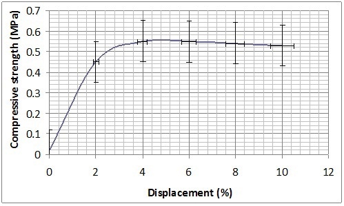
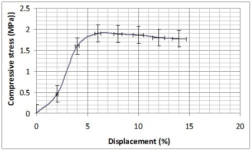
Mechanical characterization was performed on B-GP2P and B-GP2S after the complete curing at 30 days from the preparation and thermal treatment at 60 °C in Teflon® container for 150 min. Both formulations present a sort of plastic behaviour showing a long plateau before rupture at 1 MPA for B-GP2P and 2MPa for B-GP2S (Figure 8). With the high amount of silica to be activated this behavior is expected37.
(a)
(b)
Figure 8. Compression resistance of (a) B-GP2P and (b) B-GP2S after thermal treatment at 60 °C.
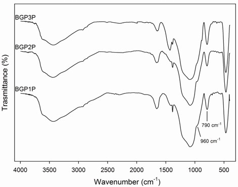
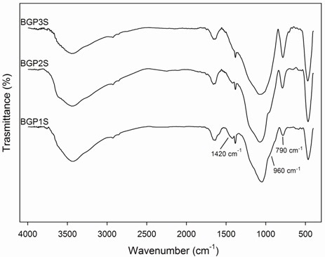
FTIR spectra (Figure 9) of potassium based geopolymers show the typical alluminosilicate vibrations presented in Table 4. Depending on thermal treatment, the bands at about 790 cm-1, due to Al(IV)-O stretching vibrations, increase and the shoulders at about 960 cm-1, due to Al(IV)-OH stretching vibrations, decrease. A possible explanation is that during the geopolymerization, there is a progressive formation of Al(IV) species and a reduction of the number of Al(IV)-OH groups. Moreover, it is evident that there are not many differences between geopolymer matrix obtained with procedure S or P (Figure 9), except for B-GP3S and B-GP3P. In B-GP3P spectrum an intense band at about 1420 cm-1 is evident due to carbonate high amount. The intensity of this band is smaller in all other spectra. Moreover, the shoulder at about 960 cm-1 decreases in B-GP3P and disappears in B-GP3S.
(a)
(b)
Figure 9. FTIR spectra of geopolymer obtained according to procedures (a) P and (b) S.
Chemical alkali activation according to procedure S, i.e. KOH pellets added to K2SiO3 solution shows some un-reacted metakaolin area in untreated B-GP1S material (Figure 10). Similar areas are present also in B-GP1P but here the platelet typical of metakaolin morphology are not so well defined indicating that alkali attack has already begun.
These areas completely disappear after the 60 °C-treatment when a more uniform microstructure is reached (Figure 11). In particular S procedure lead to more bonded microstructure as visible in Fig. 10 from the reduced number of fracture surfaces in sample B-GP2S with respect to B-GP2P, confirming what observed in the compression resistance tests.
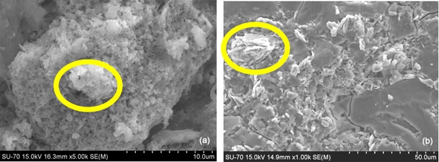
Figure 10. ESEM micrograph of (a) B-GP1P and (b) B-GP1S soon after preparation. Yellow circle evidence non reacted metakaolin area.
After the 500 °C, the microstructure maintains as in Figure 11, accordingly to infrared conclusions of very similar materials.
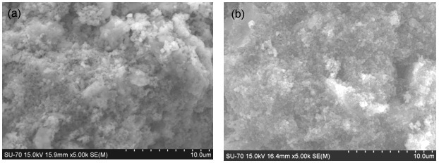
Figure 11. ESEM micrograph of (a) B-GP2P and (b) B-GP2S after 60 °C thermal treatment.
Conclusions
The study presents two formulations (GP120 and B-GP130) of metakaolin based geopolymers activated with NaOH which have been tested in vitro for bioactivity. The hydroxyl-apatite [Ca10(PO4)6(OH)2] formation was observed only on the surface of geopolymer BGP130 after immersioni n SBF solution for 21 days. Their high intrinsic compressive strength (recorded to be > 50 MPa) and the capability to form also porous structures (~60 vol. %), is indicative for their suitability for applications as hard tissue prostheses.
The third formulation proposed in the study, silica rich MK geopolymer activated with KOH/K2SiO3, has been tested mechanically to evaluate the consolidation process as a function of the activation procedure. The activation procedure that requires the addition of KOH pellets to K- silicate solution leads to materials with higher compressive strength. The results indicate that the order of addition of the reactants in the activation step is important and affects mechanical properties even though thermal consolidation is performed.
References
1. Hench L.L., “Biomaterials: a forecast for the future”, Biomaterials, 19 (16), 1419-23, 1998
2. Kim H.-W., H.-E. Kim, “Nanofiber generation of hydroxyapatite and fluor-hydroxyapatite bioceramics” J. Biomed. Mater. Res., 77B (2), 323-28, 2006
3. Ni G.X., Lu W.W., Chiu K.Y., Li Z.Y., Fong D.Y.T., Luk K.D.K., “Strontium-containing hydroxyapatite (Sr-HA) bioactive cement for primary hip replacement: An in vivo study” J. Biomed. Mater. Res. 77B (2), 409-15, 2006).
4. Oudadesse H., Derrien A.C. and Lucas-Girot A., “Statistical experimental design for studies of porosity and compressive strength in composite materials applied as biomaterials”, Eur. Phys. J. Appl. Phys., 31 (3), 217-23, 2005.
5. Oudadesse H., Derrien A., Lefloch M. and Davidovits J., “MAS-NMR studies of geopolymers heat-treated for applications in biomaterials field”, J. Mater. Sci., 42 (9), 3092-98, 2007.
6. Oudadesse H., Derrien A. C., Mami M., Martin S., Cathelineau G., Yahia L., “Alumino-silicates and biphasic HA-TCP composites: studies of properties for bony filling”, Biomed. Mater., 2 (1), S59-S64, 2007.
7. Davidovits J., “Geopolymer: Inorganic polymeric new materials”, J. Therm. Anal. Calorim., 37 (8), 1633-56, 1991.
8. Palomo A., Blanco-Varela M.T., Granizo M.L., Puertas F., Vazquez T.and Grutzeck M.W., “Chemical stability of cimentitious materials based on metakaolin”, Cement. Concrete Res., 29 (7), 997-1004, 1999.
9. Palomo A., Grutzeck M.W. and Blanco M.T., “Alkali-Activated Fly Ash: A cement for the future”, Cement. Concrete Res., 29 (8), 1323-29, 1999.
10. Van Jaarsveld J.G.S., Van Deventer J.S.J. and Lorenzen L., “The potential use of geopolymeric materials to immobilise toxic metals: Part 1. Theory and applications”, Miner. Eng. 10 (7), 659-69, 1997.
11. Cioffi R., Maffucci L. and Santoro L., “Stabilization of chloro-organics using organophilic bentonite in a cement-blast furnace slag matrix”, Resour. Conserv. Recy., 40 (1), 27-38, 2003
12. van Deventer J.S.J., Provis J.L., Duxson P. and Lukey G.C., “Reaction mechanisms in the geopolymeric conversion of inorganic waste to useful products”, J. Hazard. Mater., 139 (3), 506-13, 2007.
13. Xu H. and Van Deventer J.S.J., “The geopolymerization of aluminosilicate minerals”, Int. J. Miner. Proces., 59 (3), 247-66, 2000.
14. Hendricks W. M., Bell A. T., Radke C. J., “Effects of organic and alkali metal cations on the distribution of silicate anions in aqueous solutions”, J Phys Chem, 95 (23), 9513-18, 1991.
15. Anseau M. R., Leung J. P., Sahai N., Swaddle T.W., “Interactions of Silicate Ions with Zinc(II) and Aluminum(III) in Alkaline Aqueous Solution”, Inorg. Chem., 44 (22), 8023-32, 2005)
16. North M.R., Swaddle T.W., “Kinetics of Silicate Exchange in Alkaline Aluminosilicate Solutions”, Inorg. Chem., 39 (12), 2661-65, 2000
17. Phair J.W. and Van Deventer J.S.J., “Effect of the silicate activator pH on the microstructural characteristics of waste-based geopolymers”, Int. J. Miner. Proces., 66 (1-4), 121-43, 2002.
18. Ginebra M.P., Traykova T., Planell J.A., “Calcium phosphate cements as bone drug delivery systems: a review”. J. Control. Release., 113 (2), 102-10, 2006.
19. Kamseu E., Nait-Ali B., Bignozzi M.C., Leonelli C., Rossignol S., Smith D.S., “Bulk composition and microstructure dependence of effective thermal conductivity of porous inorganic polymer cements”, Journal of the European Ceramic Society 32 (2012) 1593–1603.
20. Barbosa V.F.F., MacKenzie K.J.D., Thaumaturgo C., “Synthesis and characterisation of materials based on inorganic polymers of alumina and silica: sodium polysialate polymers”, Int. J. Inorg. Mater. 2, 309-17, 2000.
21. Kirakosyan A., Sargsyan A., Baghramyan V., Pogosyan M., Knyazyan N., Harutjunyan N., Petrosyan G., Leonelli C., ”Uviol glass characteristics on the basis of hydrothermal charge”, XII International Conference on the Physics of Non-Cristalline Solids, Brazil, 2009, Book of abstract, p. 100.
22. Kokubo T., Takadama H., “How useful is SBF in predicting in vivo bone bioactivity?”, Biomaterials, 27 (15), 2907-15, 2006.
23. Leonelli C., Kamseu E., and Sglavo V.M., “Bi-axial four points flexural and compressive strength of geopolymer materials based on Na2O- K2O-Al2O3-SiO2 systems”, in: Developments in Strategic Materials: Ceramic Engineering and Science Proceedings, Volume 29, Issue 10 (eds H.-T. Lin, K. Koumoto, W. M. Kriven, E. Garcia, I. E. Reimanis and D. P. Norton), John Wiley & Sons, Inc., Hoboken, NJ, USA. doi: 10.1002/9780470456200.ch15.
24. Milkey R.G., “Infrared spectra of some tectosilicates”, American Mineralogist, 45, 990-1007, 1960.
25. Parker R.W., Frost R. L., “The application of drift spectroscopy to the multicomponent analysis of organic chemicals adsorbed on montmorillonite”, Clay. Clay Miner., 44 (1), 32-40, 1996.
26. Frost R.L., Fredericks P.M., Shurvell H.F., “Raman microscopy of some kaolinite clay minerals”, Can. J. Appl. Spectrosc., 41 (1), 10-14, 1996.
27. Gadsden J.A., “Infrared spectra of minerals and related inorganic compounds”, Butterworths, London, 1975.
28. Kendall K., Howard A.J., Birchall J.D., “The relation between porosity, microstructure and strength, and the approach to advanced cement-based materials”, Philos. Trans. R. Soc. London, A310, 139-54, 1983.
29. Sandeep G, H. K. Varma, T.V. Kumary, Suresh Babu S. and Annie J., “Characterization of Novel Bioactive Glass Coated Hydroxyapatite Granules in Correlation with in vitro and in vivo Studies”, Trends Biomater. Artif. Organs 19 (2), 99-107, 2006.
30. Hench L.L., “ Bioceramics: from concept to clinic”, J. Am. Ceram. Soc., 74 (7), 1487-510, 1991.
31. Takadama H., Kim H.-M., Kokubo T. “X-ray photoelectron spectroscopy study on the process of apatite formation on a sodium silicate glass in simulated body fluid”, J. Am. Soc., 85 (8), 1933-36, 2002.
32. Ohtsuki C., Kokubo T., Yamamuro T., “Mechanism of apatite formation on CaOSiO2P2O5 glasses in a simulated body fluid”, J. Non-Cryst. Solids, 143 (1), 84-92, 1992.
33. Yap A.U.J., Pek Y.S., Kumar R.A., Cheang P., Khor K.A., “Experimental studies on a new bioactive material: HAIonomer cements”, Biomaterials, 23 (3), 955 -962, 2002
34. Geyer G., Baier G., Helms J., “Epidural application of ionometric cement implants. Experimental and clinical results”, J Laryngol Otol, 112 (4), 344-350, 1998
35. Hantson P., Mahieu P., Gersdorff M., Sindic C.J.M., Lauwerys R., “Encephalopathy with seizures after use of aluminium-containing bone cement”, Lancet, 344 (8937), 1647
36. MacKenzie K.J. D., Rahner N., Smith M.E., Wong A., “Calcium-containing inorganic polymers as potential bioactive materials”, J Mater Sci, 45 (4), 999- 1007, 2010.
37. L. Keyte, “What’s wrong with Tarong? The importance of coal fly ash glass chemistry in inorganic polymer synthesis”, Ph.D. thesis, 2008, The University of Melbourne, Australia.
Contact Details
Michelina Catauro
Department of Aerospace and Mechanical Engineering,
Second University of Naples,
Via Roma 21, 81031 Aversa,
Italy
E-mail : [email protected] |
Flavia Bollino
Department of Aerospace and Mechanical Engineering,
Second University of Naples,
Via Roma 21, 81031 Aversa,
Italy
E-mail : [email protected] |
| |
|
Ishu Kansal
Department of Ceramics and Glass Engineering,
University of Aveiro,
CICECO,
3810-193 Aveiro,
Portugal.
E-mail: [email protected] |
Elie Kamseu
Department of Materials and Environmental Engineering,
University of Modena and Reggio Emilia,
Via Vignolese 905,
I-41100 Modena,
Italy
E-mail : [email protected] |
| |
|
Isabella Lancellotti
Department of Materials and Environmental Engineering,
University of Modena and Reggio Emilia,
Via Vignolese 905,
I-41100 Modena,
Italy
E-mail : [email protected] |
Cristina Leonelli
Department of Materials and Environmental Engineering,
University of Modena and Reggio Emilia,
Via Vignolese 905,
I-41100 Modena,
Italy
E-mail : [email protected] |