| New applications in coatings and surface treatment technology are helping manufacturers to overcome the cost and disruption of recurrent machinery faults caused by component wear and failure. Technologies originally developed for the aerospace and semiconductor industries are now being used to improve the wear and resilience of metal surfaces across a wide range of high performance and high temperature industrial applications. The benefits can be significant. By extending the life of tools and moulds, the technology can help to reduce plant downtime, expensive repairs and maintenance, and improve process performance. This article focuses on three technologies - ion implantation, CO2 laser surface treatment, and thermal (plasma) spraying - and examines a number of the latest applications. Ion Implantation Ion implantation has been used for 30 years to change the electrical properties of semiconductors and is now extensively used for chip-making. In the 1970s, scientists at the AEA Technology (UK) discovered that ion implantation could help to improve the wear and tribological properties of metal production tooling. Today, the process is widely used in the polymer moulding industry to treat moulds, nozzles, gates, sprues, screws and barrels. Ion implantation is a reliable and repeatable process and an ideal application for high performance, high precision components where quality is critical. The technology is becoming an integral part of tool design as its benefits are increasingly recognised, table 1. Table 1. Performance benefits produced by modifying surfaces using ion implantation. | | | Steel mould | H13 | 4x | Mould release improved | | Feed screw and barrel | Nitrided steel | 6x | Throughput improved | | Extrusion die | P20 | 4x | Improved surface finish | Advantages of Ion Implantation Compared with other treatments, ion implantation is simple, cost effective, and risk-free. The technology involves bombarding a material surface with a high-speed beam of ions. Once embedded, the ions become an integral part of the surface, without causing the adhesion and delamination problems associated with coatings. Implantation is performed at temperatures below 200°C and can be controlled to very near room temperature. It leaves the surface finish, even mirror-polished materials, totally unaltered. There is no risk of tool distortion or dimensional change. The major benefit of ion implantation for polymer tooling is its ability to change the mechanical and chemical properties of a tooling surface without affecting the substrate layers. It is possible to create exactly the surface alloy and performance characteristics required by implanting the correctly specified type and dose of ions. Applications The technology is widely used to toughen and improve the wear characteristics of moulds and tooling with fine details, textures and tight tolerance fits, where the slightest inaccuracy would be a disaster. Ions from substances such as chromium, nitrogen, carbon and oxygen can be applied to treat moulding problems such as abrasive wear from filled materials, mould release, or gas outlet corrosion. But most impressive are the results. Typically, the process can extend the life of tooling and moulds three to four times, in certain cases ten-fold, and reduce cycle times by as much as eight per cent. Case Study 1- Punch and Die Stamping Oxfordshire based Moss Plastic Parts Ltd, a manufacturer of injection moulded closures for the packaging industry, used ion implantation to help tackle recurring breakdowns of its punch and die machinery. The problem affected the stamping of twin-layer linings for resealable container caps, and occurred shortly after initial start up. High volume cycling, increasing friction, and the tendency of the twin-layered material to blunt the cutting edge, regularly caused the punch to pick up and seize in the die. This halted production until the tooling set could be disassembled, replaced and accurately reset. A specially calculated high dose ion implantation surface treatment was developed to toughen the surfaces and cutting edges of the components, improve wear resistance and reduce friction. The treatment eliminated the costly seizure problem and extended the life of the punch and die by a factor of three. The improved performance has allowed Moss to maintain the very high production rates required in the packaging industry. Case Study 2 - Wheel Trim Moulds Clearplas Ltd, manufacturer of wheel trim components for the car industry, used ion implantation to extend the wear life of its new high volume tooling, figure 1. The company had experienced problems producing the wheel trim for a range of Rover saloons, which contained 30% glass filler for added impact resistance. Because the filler was highly abrasive in production, the moulds had to be stripped and polished repeatedly. Without regular treatment, the moulds (worth £60,000 each) would wear rapidly, causing product quality problems and production overruns. | 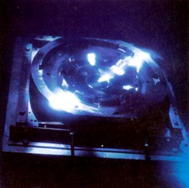
| | Figure 1. A 3810mm wheel trim mould for a standard saloon car. Lifetime increased by ion implantation. | To accommodate the large scale of the wheel trim moulds, AEA Technology used a specially developed one metre diameter beam, unusual for ion implantation where beams the size of a postage stamp are more common. The process produced dramatic results, a four-fold improvement in wear resistance and reduced friction, resulting in improved material flow and reduced cycle times. CO2 Laser Surface Treatment Another technique improving the toughness and hardness of metals in high performance applications is CO2 laser heat treatment. The benefit of laser treatment is the accuracy and control with which a large amount of energy can be projected into a well-defined area in a very short time. Using computer-controlled optical methods, figure 2, the beam can be focused and moved quickly to ensure that only very precisely defined areas are covered. Significantly, the speed of the laser process and the relatively low amount of energy put into the material leaves the material under the surface layer totally unaffected. | 
| | Figure 2. Schematic of a CO2 laser treatment setup. | As the beam is scanned over a steel surface, the temperature of a shallow surface layer of up to 1.5mm rises dramatically. With the correct beam width and scan speed the temperature can be raised above its hardening point. At the moment the beam moves on and the heating ceases, the heat in the surface layer is transferred into the cold material below the surface. This rapid quench creates a very high degree of hardness at the steel surface. Advantages and Disadvantages The cost of laser equipment is relatively high, but can be largely offset by a number of benefits. It can treat components in their finish-machined condition, without the need for expensive regrinding operations. It offers high utilisation levels, since the beam can be quickly switched between alternate workstations. Finally, the technique copes well with a wide range of component sizes and can even be applied in retreating service worn components. Case Study 3 - Piston Groove Hardening Diesel engine manufacturer AE Goetzer, part of auto components group Turner & Newell, used laser hardening treatment on piston components to help extend the maintenance interval between engine overhauls. Medium speed diesel engines have traditionally used aluminium pistons with reinforced upper ring grooves. When the company switched to tougher steel and cast iron pistons, it discovered rapid wear at the ring groove faces, particularly when using lower grade fuels. Attempts to use induction hardening to increase the durability of the piston proved unsuccessful. Laser hardening using optical beam scanning equipment provided a solution. The technique achieved groove hardening in both steel and cast iron pistons to a depth of 0.5mm without surface melting or significant distortion of the sensitive region around the groove land. The project enabled the company to double the lifetime of the pistons, and thereby meet its overall objective. Thermal (Plasma) Spraying Unlike ion implantation, thermal (or plasma) spraying is a coating technology. It was developed in the 1960s to protect jet turbine components from excessive heat and wear. The technology involves a series of processes in which powdered material, in a molten state, is bombarded onto a surface to build up a metal or ceramic coating. The resulting coatings bond well and a wide range can be applied, since the high temperature plasma can melt any metal or ceramic powder. Case Study 4 - Furnace Susceptors Temperatures in the manufacture of furnaces for optical fibre production often exceed 2000°C. Not surprisingly, key components such as heating elements can have a very short life. In the case of Stanelco Products, the traditional graphite and early zirconia susceptors used as heating elements in its furnaces lasted for only seven to ten days. The company turned to AEA Technology to redesign its yttria stabilised zirconia susceptors, figure 3, which although more durable were still not economically viable. The solution was a novel plasma generated twin walled (duplex) tube arrangement that was able to withstand thermal shock at temperatures up to 2400°C. The more rigid double-walled design increased the life of the new susceptors to three months, and in some cases up to a year, 50 times longer than the previous components. | 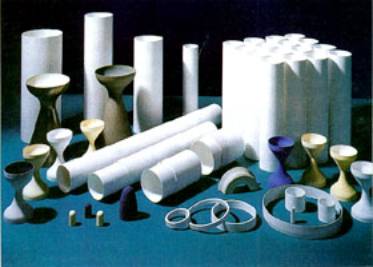
| | Figure 3. A range of furnace liners, or susceptors, used in pulling towers for the manufacture of optical fibre, and near net shapes produced by thermal spraying. | The design also prevented the ingress of contaminants into the surface. Even if a single wall breaks during operation, no stray particles can enter the surface. A further benefit is the reduced risk of fibre breakage. Contaminants can become attached to the fibre, causing breakages that would be disastrous during the fabrication of a 30km length of optical fibre. The new susceptors allow the manufacture of long tow length production runs in pulling towers with reduced risk of fibre breakage. They also cut down the downtime that results from having to replace the susceptors frequently. Plasma spray susceptors can be produced in a vast range of tube sizes to extremely accurate length and bore sizes. The technology can also produce other near-net shape components such as elements, crucibles, radomes and rocket nozzles. |