Introduction The ceramic/metal joints have been increasingly applied in a wide range of engineering fields because the ceramic has stable mechanical properties at high temperature and good resistance to wear, erosion and oxidation. However, the difference of material properties between metal and ceramic induces stress singularities at the interface edge. Moreover, high thermal residual stress will be induced during the cooling process due to the mismatch of the thermal expansion coefficients. The stress singularity together with the thermal residual stress degrades the strength of ceramic/metal joint and makes the evaluation of the strength difficult. Many works have been done about the residual stress and the strength evaluation of ceramic/metal joints. For example, Kobayashi et al. [1, 2] have investigated the bending strength and residual stress of Si3N4/S45C joint and the effect of the size of the specimen on the bending strength. Qiu et al. [3] have investigated the influence of residual stress and cyclic load on the strength of Si3N4/S45C joint. However, due to the complexity of the problem, a generalized evaluation method for the ceramic/metal joint has not yet been proposed. The elastic solution of the singular stress field of the interface crack has been studied since 1959 [4-9]. Rice [10] has summarized the work in this field and set up the elastic fracture mechanics concepts for interfacial cracks. Yuuki et al. [11, 12] have proposed the maximum normal stress criteria for predicting fracture path and strength of ceramic/metal joint based on the elastic theory. The plastic deformation of metal will inevitably appear near the crack tip due to the stress singularity. For most of the ceramic/metal joints, the plastic deformation of metal has a significant influence on the strength of the ceramic/metal joint. Due to the analytical complexity, the evaluation of the fracture path and strength of ceramic/metal joint based on the elasto-plastic theory has not yet been made. In this study, four point bending tests of Si3N4/S45C joint specimens with an interface crack were carried out. Evaluation of the fracture path and fracture toughness was attempted based on the elasto-plastic analysis. Experimental Specimen Preparation Figure 1 shows the geometry and dimensions of Si3N4/S45C joint specimen. The silver based brazing alloy (wt% is: Ag, 71%, Cu, 27%, Ti, 2%) with 60 μm thickness was used for the bonding between Si3N4 ceramics and S45C steel. Brazing was carried in a vacuum furnace (2.5x10⁻⁵ Torr). The temperature of the furnace was increased at a rate of 20oC/min up to the brazing temperature of 850oC and kept for 10 min, then decreased at a rate of 10oC/min. The joining surfaces were polished with diamond powder of 0.25 μm diameter. During the brazing, a contact pressure of 0.002 MPa was applied. After brazing, an interface crack was introduced by the electric discharge method with the cutting wire of 0.1 mm diameter. Four specimens with different crack lengths were prepared. Two of the specimens had crack lengths of 4.0 mm and the other two specimens had crack lengths of 1.0 mm and 2.0 mm. | 
| | Figure 1. Fracture toughness specimen. | Experimental Results Four point bending tests were carried out on the fracture toughness specimens at a crosshead speed of 0.5 mm/min. Table 1 shows the results of the fracture toughness. The apparent fracture toughness is defined as:  (1) (1)
with  (2) (2)
 (3) (3)
Where Pf is the fracture load, a is the crack length, w the specimen width, t the specimen highness, L2 the outer span and L1 the inner span. Table 1. Result of the fracture toughness tests. | | | 1 | 1.0 | 285.4 | 17.128 | 1.0436 | 0.9807 | | 2 | 2.0 | 237.8 | 14.27 | 1.0530 | 1.1607 | | 3 | 4.0 | 1649.0 | 98.95 | 1.2561 | 12.4317 | | 4 | 4.0 | 1744.2 | 104.65 | 1.2561 | 13.1478 | As can be seen in Table 1, the specimens with a crack length of 4.0 mm indicate a higher fracture load than those with shorter crack lengths of 1.0 and 2.0 mm. As the residual stress will redistribute after cutting [2], the relaxation of thermal residual stress for longer crack length may be a possible reason. Figure 2 shows the macroscopic observation of the fractured specimen. For the specimens with a crack length of 1.0 and 2.0 mm, crack propagated into Si3N4 directly from the initial crack tip in the direction of about 40o. For the specimens with a crack length of 4.0 mm, the crack propagated along the interface for about 1.0 mm and then kinked into Si3N4 in a direction of about 10o to the interface. | 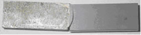
(a) a = 1.0mm 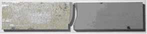
(b) a = 2.0mm 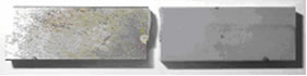
(c) a = 4.0mm 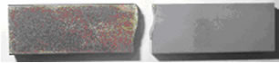
(d) a = 4.0mm | | Figure 2. Fractured specimens. | Oscillatory Singular Stress Field of The Interface Crack and The Maximum Normal Stress Criteria The elastic solution of the stress field of an interface crack has been accomplished by the Willims [4], Erdogan [5, 6], England [7] and Sih et al. [8, 9]. It has been found that the stress field near the interface crack tip has the oscillatory singularity. Under the polar coordinate with the origin located at the crack tip, the stress field can be expressed as  (4) (4)
Here  is the bi-material constant that can be expressed as is the bi-material constant that can be expressed as  (5) (5)
 (6) (6)
where µj and vj are the shear modulus and the Poisson’s ratio of the materials, respectively. The stress intensity factors of the oscillatory singular stress field are defined as  (7) (7)
where, l is the reference length to eliminate the dimension of the oscillatory term. Usually l takes the value of the whole crack length, i.e. l=2a. When the stress along the interface has been known, the stress intensity factors can be can be extrapolated as:  (8) (8)
 (9) (9)
Yuuki et al. [11, 12] have proposed up the maximum normal stress criteria for the fracture of interface crack. Considering that the value of  is very small, the normal stress can be approximately expressed as is very small, the normal stress can be approximately expressed as  (10) (10)
where  (11) (11)
W1= e-ε(π-θ), W2= eε(π+θ) (12)  (13) (13)
The direction of the maximum normal stress can be determined from: ∂B(θ,ε,y)/∂ θ = 0 (14) Let θ0 represent the direction of the maximum normal stress, the corresponding stress intensity factor can be expressed as:  (15) (15)
Fracture will occur along the direction of θ0 when Kθmax reaches the KIC value of the base material. It should be noted that fracture may occur along the interface when θ0 becomes smaller than certain value, since the strength of interface is usually lower than that of the base material. Elasto-Plastic Singular Stress Field at The Interface Crack Tip The elasto-plastic singular stress field for a linear hardening material [13] has been found to be substantially the same as that of elastic material whose elastic constants are defined as:   (16) (16)
where E is the Young’s modulus and H’ the hardening coefficient. Therefore, the elasto-plastic singular stress field at the interface crack tip is substantially the same as the elastic singular stress field of the interface crack tip. The governing region of the elasto-plastic singular stress field will be confined in a small region around the crack tip inside the yield zone. For ceramic/metal joint, considering that the value of hardening coefficient is much less than the value of Young’s modulus, it can be found from Eq. (16) and Eq. (5) that  (17) (17)
FEM Analysis and Evaluation of Fracture Path and Toughness Based on the Elasto-Plastic Stress Intensity Factors FEM analysis was carried out under plane stress condition using the program of ABAQUS. Si3N4 is assumed as an elastic material whose material constants are independent of temperature and E=289 GPa, v=0.25 and CTE=4.2x10⁻⁶. S45C steel is assumed as a linear hardening material with the material constants listed in Table 2 [14]. The stress free temperature is considered to be 550oC for the analysis of the thermal residual stress. Table 2. Material constants of S45C | | | E (GPa) | 206 | 206 | 201 | 197 | 192 | 187 | 183 | | v | 0.3 | 0.3 | 0.3 | 0.3 | 0.3 | 0.3 | 0.3 | | σY- (MPa) | 375 | 348 | 333 | 309 | 280 | 241 | 193 | | H’ (MPa) | 1381 | 2056 | 2680 | 2325 | 1685 | 1026 | 687 | | CTE (10-6) | 11.71 | 12.17 | 12.63 | 13.09 | 13.55 | 14.01 | 14.47 | For comparison, the elastic analysis was also carried out. Calculated from the elastic constants of 25oC, the bi-material constant for elastic case is 0.01588. Table 3 lists the stress intensity factors as well as the direction of the maximum normal stress obtained by the elastic analysis. It can be found that the for elastic case is 0.01588. Table 3 lists the stress intensity factors as well as the direction of the maximum normal stress obtained by the elastic analysis. It can be found that the  value due to residual stress is much higher than value due to residual stress is much higher than  and the values of θ0 due to the residual stress are almost the same, which are about 70o. The specimen with a crack length of 2.0 mm has the maximum value of Kθmax due to the residual stress. The values of Kθmax due to superposition of residual stress and applied stress during fracture toughness test are close to those due to the residual stress. and the values of θ0 due to the residual stress are almost the same, which are about 70o. The specimen with a crack length of 2.0 mm has the maximum value of Kθmax due to the residual stress. The values of Kθmax due to superposition of residual stress and applied stress during fracture toughness test are close to those due to the residual stress. Table 3. Stress intensity factors and the direction of the maximum normal stress according to the elastic analysis. | | | a=1mm | K1=1.50 K2=21.05 | 25.79 | 69o | K1=2.5 K2=21.7 | 26.45 | 68o | | a=2mm | K1=0.5 K2=25.4 | 29.52 | 70o | K1=1.63 K2=25.42 | 30.21 | 69o | | a=4mm | K1=-0.01 K2=24.8 | 28.54 | 71o | K1=14.0 K2=25.1 | 37.69 | 61o | However, the results of elastic analysis apparently contradict with that the value of Kθmax is much higher than KIC value of Si3N4, which is about 6.0 MPa√m [15]. Also, the elastic analysis cannot explain why the specimen with a=4.0 mm indicates higher fracture load than the specimen with a=1.0 mm since Kθmax due to the residual stress for a=4.0 mm is larger than that for a=1.0 mm. Figures 3 and 4 show the stress distribution the interface obtained by the elasto-plastic analysis. A line with the slop of –0.5 is also plotted in the figures for reference. We can see that the curves are almost parallel to the reference line in the region r<10-6m, which indicates that the stress near the crack tip is dominated by the elasto-plastic singular stress field. | 
| | Figure 3. Normal stress distribution along the interface. | | 
| | Figure 4. Shear stress distribution along the interface. | Figures 5 and 6 show the uncoupled components defined by Eq. (8) and Eq. (9). Different from the elastic case, here the reference length l takes the value of 1.0-6 m, which is close to the size of governing region of the elasto-plastic singular stress field. Figure 5 shows stress distribution due to residual stress and Figure 6 shows the stress distribution due to residual stress and applied load. It can be found that the curves are almost parallel to reference line in the region r<1.0-5 m. | 
| | Figure 5. Distribution of the decoupled components along the interface for the residual stress. | | 
| | Figure 6. Distribution of the decoupled components along the interface at the fracture of specimen. | Table 4 lists the stress intensity factors and the directions of maximum normal stress obtained by the elasto-plastic analysis. It can be found that Kθmax due to residual stress decreases in the sequence of a=2.0 mm, a=1.0 mm and a=4.0 mm. This result can explain why the specimen with a crack length of 4.0 mm indicates higher fracture load compared to the other specimens. The applied load tends to decrease the value of K2. The decrease of K2 for a=4.0 mm is especially obvious and the value of θ0 for a=4.0 mm is 33o, which is much smaller than those for a=1.0 mm and a=2.0 mm. This agrees with the experimental result, where the specimens with a=1.0 mm and a=2.0 mm fractured with an angle of about 40o from the interface, while the specimens of a=4.0 mm fractured along the interface. The values of Kθmax due to residual stress and applied stress, that is when fracture occurred, are almost the same regardless of the crack length. They are also close to the KIC value of Si3N4, although less than it. Kobayashi et al [1] have found in the bending tests of Si3N4/S45C joint that the results can be divided into two groups, in which one shows a relatively high strength while the other shows a very low value. One reason for a low strength is considered to be the existence of a crack in the ceramic, since the cracks are easily initiated from the inherent defect during cutting after joining. This can be also considered to be one of the reasons why the Kθmax values when fracture occurred are less than the KIC value of Si3N4. Table 4. Stress intensity factors and the direction of the maximum normal stress according to the elasto-plastic analysis. | | | a=1mm | K1=-0.15 K2=2.51 | 2.68 | 71o | K1=0.43 K2=2.50 | 3.09 | 67o | | a=2mm | K1=-0.22 K2=2.80 | 2.95 | 71o | K1=0.78 K2=2.76 | 3.65 | 65o | | a=4mm | K1=-0.30 K2=2.45 | 2.51 | 72o | K1=3.82 K2=0.76 | 4.28 | 33o | Conclusions Fracture toughness tests were carried out on Si3N4/S45C joint specimens with interface cracks of different lengths. Evaluation of fracture path and fracture toughness was carried out based on elasto-plastic analysis in which S45C steel was assumed as a linear hardening material. The conclusions obtained can be summarized as: • The thermal residual stress has a significant effect on the fracture toughness of the joint. Due to the effect of residual stress, the specimen with a crack length of 4.0 mm has higher fracture toughness than those with crack lengths of 1.0 mm and 2.0 mm. A crack propagated into Si3N4 directly from the initial crack tip in the direction of 40o for crack lengths of 1.0 mm or 2.0 mm, while it propagated along the interface for the crack length of 4.0 mm. • Stress near the crack tip is dominated by the elasto-plastic singular stress field. Maximum σθ criterion based on the elasto-plastic singular stress field could be successfully applied for evaluating the fracture path and fracture toughness value. 3. Kθmax value due to the residual stress decreases in the sequence of a=2.0 mm, a=1.0 mm and a=4.0 mm. This is the same sequence of fracture load of the specimens with a=2.0 mm, a=1.0 mm and a=4.0 mm. The applied stress resulted in a decrease of the value of K2. The decrease of K2 for a=4.0 mm was significant and the value of θ0 for a=4.0 mm was much smaller than those for a=1.0 mm and a=2.0 mm. This agrees with the experimental result that the specimens with a=1.0 mm and a=2.0 mm fractured with an angle of about 40o to the interface, while the specimens of a=4.0 mm fractured along the interface. The Kθmax values at the fracture of specimens were almost same for all the specimen and were close to the KIC value of Si3N4. References 1. H. Kobayashi, Y. Arai, H. Nakamura and T. Sato, “Strength Evaluation of Ceramic-Metal Joints”, Materials Science and Engineering, A143 (1991) 91-102. 2. H. Kobayashi, H., Nakamura, A. Todoroki, W. Park, T. Koide and H. Taniai, Effect of specimen cut off and size on bending strength of ceramic/metal joints, Trans. of JSME, A60-569 (1994) 65-70. 3. J.H. Qiu, S. Nakamura, M. Kawagoe and M. Morita, “Influence of Joining Strength of Si3N4/S45C on Residual Stress”, Journal of Inorganic Materials, 13-4 (1998) 167-172. 4. M.L. Williams, “The Stress Around a Fault or Crack in Dissimilar Media”, Bulletin of the Seismological Society of America, 49-2 (1959) 199-204. 5. F. Erdogan, “Stress Distribution in Bonded Dissimilar Materials with Cracks”, J. Appl. Mech., 32 (1965) 403-411. 6. F. Erdogan, “Stress Distribution in Bonded Dissimilar Materials Containing Circular Ring-shaped Cavities”, J.Appl.Mech., 32 (1965) 829-836. 7. A. H. England, “A Crack between Dissimilar Medias”, J. Appl. Mech., 32 (1965) 400-407. 8. G..C. Sih and J. R. Rice, “The Bending of Plates of Dissimilar Materials with Cracks”, J. Appl. Mech., 31 (1964) 477-483. 9. J. R. Rice and G.C. Sih, “Plane Problems of Cracks in Dissimilar Media”, J. Appl. Mech., 32 (1965) 418-423. 10. J. R. Rice, “Elastic Fracture Mechanics Concepts for Interfacial Cracks”, J. Appl. Mech., 55 (1988) 98-103. 11. R. Yuuki and J.Q. Xu, Eng. Fract. Mech., “Stress Based Criterion for an Interface crack Kinking out of the Interface in Dissimilar Materials”, 41-5 (1992) 635-644. 12. R. Yuuki, J.Q. Xu and Y. Mutoh, “Evaluation of Fracture and Strength of Metal/Ceramic bonded Joints Based on Interfacial Fracture Mechanics”, Trans. of JSME, A60-569 (1994) 37-45. 13. J.Q. Xu and L. Fu, “Stress Field near an Interface Edge of Linear Hardening Materials”, Journal of Zhejiang University: Science V No.3-1 (2002) 13-18. 14. N. Okabe, M. Takahashi, X. Zhu, K. Kagawa and M. Maruyama, “Residual Stress and Fatigue Strength Properties of Ceramic/Metal joints”, J. Soc. Mat. Sci., Japan, 48-12 (1999) 1416-1422. 15. Y. Mutoh and I. Yumoto, “Fracture Toughness Evaluation for Ceramics/Metal Joints”, Trans. of the Symposium of Material Mechanics of JSME, No.900-50 (1990) 185-190. Contact Details |