|
Scanning electron microscopy (SEM) has long played a central role in structural characterisation for material scientists. Bombarding the surface of a material with a beam of electrons and detecting those that are emitted or backscattered allows microscopists to see down to resolutions of 10 nanometres or so, giving them intricate details of the material’s structure. However, the requirements of SEM, such as a high vacuum and the need for a thin coating if an insulator is being analysed, mean that certain types of materials have always proved difficult or impossible to image straightforwardly.
Limitations of Conventional SEM
For example, the coating can obscure the fine surface detail on some insulators - although SEMs equipped with field emission guns have made such samples easier to image. Another difficulty arises with wet and damp samples such as paints, inks, emulsions and biological tissue - these materials prove particularly challenging for SEM. The high vacuum requirements in the chamber mean lengthy specimen preparation techniques are required to remove or fix the water before imaging, raising the risk of artefacts being introduced.
Overcoming These Limitations Using ESEM
These problems can now be overcome, thanks to the new environmental scanning electron microscope (ESEM), which permits the imaging of wet systems with no prior specimen preparation. The development of this instrument means that whole new classes of materials, previously undreamed of, can be imaged in their natural state. But the potential of ESEM is even greater than. this. Because the sample environment can be dynamically altered, hydration and dehydration processes can be followed as they happen in the sample chamber.
How Are These Limitations Overcome?
So how is this all achieved? Two basic developments have made it possible for this new generation of SEMs to hit the market. Firstly there was the recognition that by using a system of differential pumping, the electron gun can be maintained at high vacuum while the sample chamber can be kept at a constant pressure of 10-20 torr (1 torr ~ 133 N.m-2).
Pressure Limiting Apertures
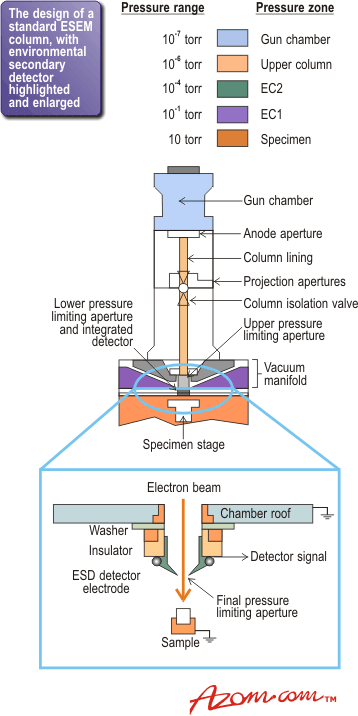
In the ESEM instrument, a series of pressure limiting apertures (PLAs) are placed down the column, across each of which a pressure differential is maintained. Figure 1 shows the column and highlights the pressures in the different zones. Consequently, despite the relatively high pressure in the chamber, this design allows ESEMs to operate with LaB6 filaments as well as tungsten, and field emission guns are also becoming available to give superior quality imaging.
|
|
|
Figure 1. The design of a standard ESEM column with the environmental secondary detector highlighted and enlarged.
|
Detectors
Having a vapour in the sample chamber presents another problem - the conventional Everhardt-Thornley detector used to pick up the electrons emitted from the sample surface in standard SEM cannot be used for ESEM. So the second crucial development needed was a new type of detector that can operate at a pressure of tens of torrs. The enlarged section in figure 1 shows the environmental secondary detector, which was the first successful detector to operate under these conditions. As its development has been only fairly recent, detector design is still being modified and optimised.
Electron Beam Scattering and Resolution
Scattering of the electron beam between the gun and the sample is an obvious concern, given that there are many atoms/molecules of vapour in the ESEM’s chambers. The question is: if such scattering occurs, can a decent resolution be achieved? The answer is yes, as long as the gap between the final PLA and the sample is kept reasonably small, say 510 mm, and the pressure is kept quite modest, say less than 12 torr.
Under these circumstances, with a mean free path for 20 KeV electrons of a few millimetres, the majority of incident electrons from the gun are not scattered at all. A well defined electron ‘probe’ is still incident on the sample, but with an accompanying ‘skirt’ of scattered electrons which can extend for tens of microns from the central probe. Fortunately, the intensity distribution of the skirt is quite flat and so it can essentially be treated as a background signal, above which the central probe still gives a strong signal. In fact, the probe signal is strong enough to give a resolution of down to 5nm with a LaB6 filament, if the pressure in the sample chamber is kept sufficiently low.
Backscattered Electrons
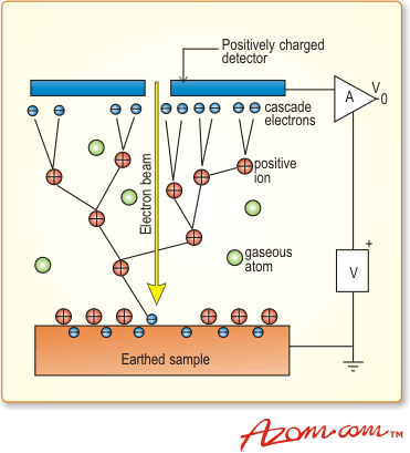
Of greater importance is what happens to the electrons - both those ‘backscattered’ from the sample surface and ‘secondaries’ produced by the surface bombardment - after they leave the sample and move towards the detector. Owing to the presence of the vapour, these electrons also undergo collisions, many of which lead to ionisation of a gas molecule (particularly in the case of the low energy ‘secondaries’). Each ionisation produces a daughter electron, which can then itself ionise further gas molecules, creating a cascade in the gap between sample and detector, figure 2. The overall effect is considerable signal amplification the extent of this depends on parameters such as gas pressure and type, detector bias and of course the population of electrons leaving the sample.
|
|
|
Figure 2. The cascade amplification process.
|
Wet Imaging
As vapour is tolerated in the sample chamber, ESEM makes it possible to carry out ‘wet imaging’ of samples. In order to view a wet sample such as a colloidal dispersion, the atmosphere in the sample chamber must be carefully controlled at all stages. After the sample is placed in the chamber, air at atmospheric pressure must be replaced by water vapour at a few torr It is important to carry out the pump-down carefully so that premature dehydration of the dispersion does not occur. If done correctly, no accidental aggregation of the particles occurs, and a truly dispersed state will be imaged.
Evaporation and Condensation
During imaging it is also important to ensure that neither water evaporation nor condensation occur. This is achieved by using an atmosphere at the saturated vapour pressure (SVP) of water. However, this raises an additional difficulty in imaging samples at room temperature, because the SVP of water is relatively high at this temperature compared to the modest pressures of a few torr that are acceptable in the sample chamber. The trick is to use a Peltier stage to drop the temperature by a few degrees so that SVP is easily maintained without undue loss of image quality and resolution.
Real Time Hydration/Dehydration Studies
However, for certain experiments it is desirable to move away from these SVP equilibrium conditions to allow deliberate hydration or dehydration of a sample. In principle, changes in structure or state of a wet sample can be dynamically followed as water condenses on to or evaporates from the sample. In practice though, beam damage - always a bugbear for electron microscopists and a particular problem when examining organic materials - may well prevent real time studies being carried out.
It may therefore be necessary to examine the structure by viewing different samples at different times during the hydration or dehydration process. Dropping the temperature to cause water to condense onto a sample surface can be just as useful an experiment. Chemical reactions taking place in water can be followed in this way.
Case Study – Hydration of Cement
The hydration of cement is one important example of a chemical reaction in water that can be followed using the ESEM. Cement is an extremely important and complex commercial material. Controlling the reaction of the grains of material with water is vital in ensuring that the cement sets at the right rate - too fast and it could, say, plug a deep sea oil well, too slow and it holds up construction. Despite its importance, there are still uncertainties about the precise mechanisms involved in the setting process and about how subtle changes in cement composition may affect it. ESEM can look at the developing structure in the cement at different times during the setting reaction.
Cement has a number of different inorganic ingredients, including tricalcium silicate (C3S), tricalcium aluminate, dicalcium silicate, tetracalcium aluminoferrite and gypsum. Within the limited field of view of the microscope it is difficult to examine the individual reactions of each component, and so it is easier to follow the reactions of the components separately.
Initially, water is condensed onto a dry grain by dropping the sample temperature, and the reaction is then allowed to proceed for the required length of time. ESEM cannot produce an image through a significant thickness of water, however, so after this time the sample temperature is raised slightly to evaporate most of the surface water. Only a thin, electron-transparent layer remains, to keep the grain hydrated. By repeating this process, the evolving structure can be followed and related to measurements made by other techniques, such as calorimetry.
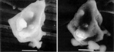
Figure 3 shows a single grain of C3S before and after 2 minutes of hydration. Using images such as these it has been possible to confirm the hypothesis that a semi-permeable membrane forms after an initial rapid reaction between the water and the C3S. This membrane drastically slows down subsequent reactions, corresponding to the apparent period of dormancy that has previously been identified by thermal analysis. Eventually, enough. ions cross this membrane to allow further reaction to take place, which is revealed by the formation of hexagonal calcium hydroxide grains.
|
|
|
Figure 3. A grain of tricalcium silicate when dry (left) and after 2 minutes of hydration (right). Exposure to water permits the formation of a semi-permeable membrane around the particle, which slows down subsequent reactions.
|
A note of caution is in order. Although this ESEM analysis requires minimal sample preparation and so might be expected to be artefact-free, problems may still arise due to incorrect experimental procedures. In the case of C3S, it might seem an attractive idea to study one single grain repeatedly as the reaction proceeds over a number of hydration/dehydration cycles. However, this cycling changes the distribution of ions in the grain, and calcium hydroxide crystals appear long before the predicted end of the dormancy period. So despite appearing attractive, this procedure gives misleading results, and it is necessary to look at a new grain for each different stage of the reaction being examined.
Applications of ESEM
ESEM has a number of different applications already, but there is plenty of opportunity to extend this range of uses. ESEMs have been around for a number of years, with more in the US than elsewhere, yet as a technique it appears to be substantially underexploited. This is perhaps especially true of its application to studying wet systems. In part this can be attributed to an early failure to appreciate the careful control of chamber pressure required at all times. With improving awareness of this, ESEM will find a key role in an increasing number of materials characterisation laboratories.
Summary
ESEM is also staking a claim to be a separate technique from SEM. It would be wrong to think of the ESEM as simply a ‘leaky’ SEM. It is becoming apparent that, whereas secondary electrons in SEM basically yield topographic contrast and backscattered electrons show atomic number, ESEM may produce a contrast mechanism with no SEM equivalent. This means that not only are new classes of samples accessible or the first time, but conventional samples such as semiconductors may be examined in new ways. Of particular interest is the fact that ESEM may be sensitive to the electronic structure of the material, owing to the absence of a surface coating and the way that cascade amplification occurs. Although work on this aspect of ESEM is still in its infancy, this finding seems likely to lead to a rapid growth in ESEM activity in the future.
|