Sep 30 2021
Modern wireless communication equipment relies on advanced radio frequency (RF) microelectromechanical devices. Wireless communication finds various applications such as mobile communication devices used in vehicles and aviation, global positioning systems (GPS), and military satellites.

Image Credit: Fit Ztudio/Shutterstock.com
The advent of fifth-generation mobile communication technology (5G) has rendered the frequency spectrum, quality, and characteristics of filters used in wireless devices much more crucial in higher frequency bands.
Acoustic wave filters are more significantly used for this purpose and can be divided into surface acoustic wave (SAW) filters and bulk acoustic wave (BAW) filters. BAW filters can easily achieve a high-frequency range of more than 2 GHz and feature a smaller volume, excellent device characteristics, higher power endurance, and a wider application frequency range.
This makes them highly valued in future mobile communication applications.
A BAW resonator includes a piezoelectric film, where face-etched, back-etched, and solidly mounted structures are commonly used to prevent the loss of sound wave energy from the substrate.
Solidly mounted resonators (SMRs) include a Bragg reflector that either prevents the sound wave energy from escaping the substrate or reflects the sound wave energy back into the piezoelectric layer to ensure a stable structure and high yield.
BAW devices are mainly based on aluminum nitride (AlN) and zinc oxide (ZnO) as piezoelectric materials, which are excellent piezoelectric materials. However. due to the current trend of high-frequency communications, AlN has gained more attention.
Researchers have adopted various methods to improve the kt2 value of a piezoelectric material. ScN, with its hexagonal structure, contributes to the piezoelectricity of ScxAl1−xN (x < 0.5) thin films.
Sc-IIIA-N compounds have excellent piezoelectric properties. Of the IIIA compounds, AlN has the highest Curie temperature and thermal stability.
Therefore, AlN and Sc can be combined to form ScxAl1−xN alloy films as novel piezoelectric materials for acoustic wave components.
Materials and Methods
This article describes the development of a 3.5-GHz SMR using an AlScN piezoelectric film.
A low-roughness Bragg reflector was deposited on the substrate to prevent the dissipation of acoustic wave energy. The SMR structure can be divided into two modes: λ/4 mode and λ/2 mode.
A λ/2 mode resonator was adopted in this study, where λ is the resonance wavelength.
Figure 1 shows a free interface between the Bragg reflector and the piezoelectric layer in the SMR structure. In general, the piezoelectric film is a λ/2 type resonator with a larger effective electromechanical coupling coefficient than that of the λ/4 type resonator.
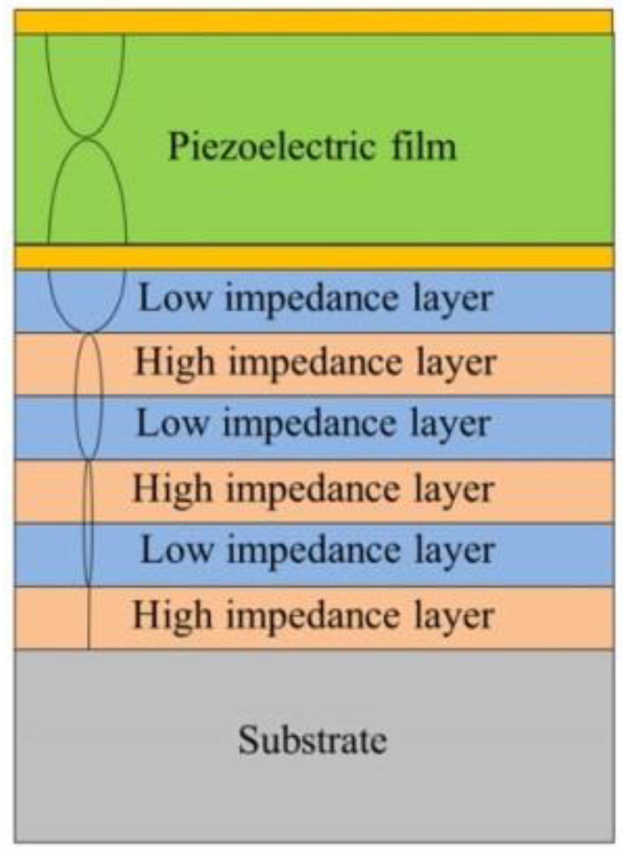
Figure 1. The schematic of a λ/2 mode resonator. Image Credit: Coatings 2021
High-acoustic-impedance material molybdenum (Mo) and low-acoustic-impedance material silicon dioxide (SiO2) were used as the reflective high and low impedance layers, respectively, to develop the Bragg reflector on Si substrate.
An Al(85%)-Sc(15%) alloy target was used to deposit AlScN piezoelectric films.
The characteristics of the piezoelectric film were analyzed to identify the optimal sputtering parameters.
The surface and cross-sectional structures of the films were analyzed under various sputtering conditions. The crystalline orientation and the peak strength of X-ray diffraction of AlScN film were analyzed to determine its optimal sputtering parameters.
Thus, the required thickness of the piezoelectric film was determined to fabricate SMR devices.
In BAW devices, the resonator bandwidth, insertion loss, and resonance frequency are governed by the effective electromechanical coupling coefficient kt2 and the thickness of the piezoelectric layer.
Thus, a thin film with low acoustic wave loss and a high electromechanical coupling coefficient is critical.
The electromechanical coupling coefficient is directly proportional not only to the effect of conversion of mechanical energy to electrical energy but also to the bandwidth of the combined filter.
The parallel resonant frequency fp (ωp) at which the imaginary part of the impedance is maximum and the series resonant frequency fs (ωs) at which the imaginary part of the impedance is zero determine the effective electromechanical coupling coefficient.
In this study, three pairs of Bragg reflectors were formed by alternately depositing Mo and SiO2 films—with a thickness of 449 and 371 nm, respectively—on a p-type (100) Si.
A Ti seed layer and the bottom Mo electrode were deposited. The overlying film AlScN was then deposited above the bottom electrode. The Mo/Ti top electrode was fabricated on the piezoelectric film.
An electrical connection with the bottom electrode was achieved by thorough hole patterning. AlScN was etched with phosphoric acid at 90 °C, and thus a λ/2 mode SMR was fabricated.
Figure 2 illustrates the flowchart of the fabrication process. Figure 3 depicts the 3D representation of the structure of a solidly mounted resonator.
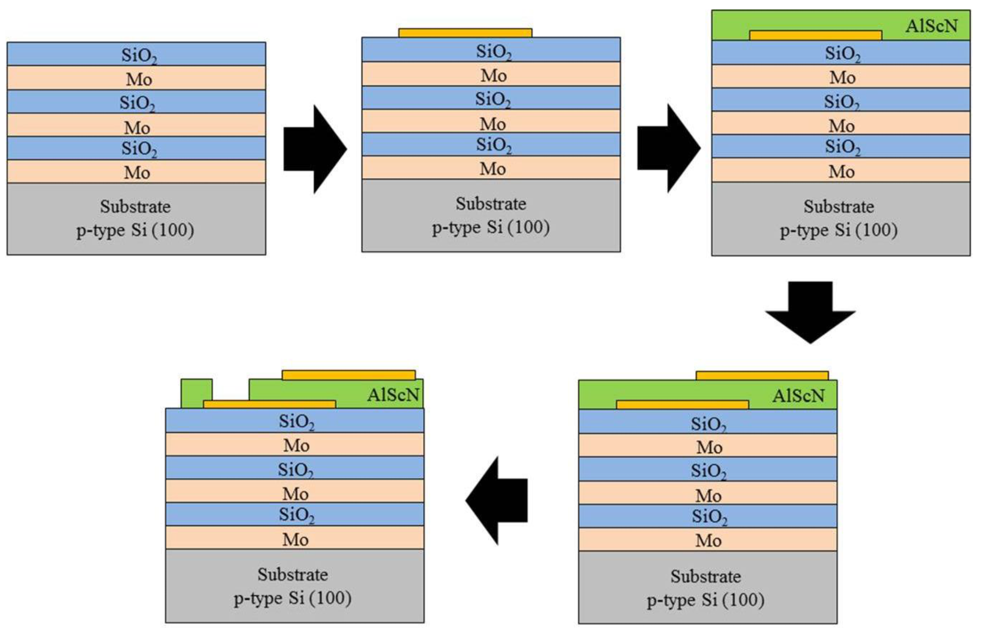
Figure 2. The flowchart of the fabrication process of the designed SMR device. Image Credit: Coatings 2021

Figure 3. 3D representation of the structure of a solidly mounted resonator. Image Credit: Coatings 2021
Results and Discussion
The surface of the Bragg reflector should be as flat as possible to limit acoustic energy and prevent acoustic scattering.
The DC and RF magnetron sputters were precisely controlled, and the optimal sputtering parameters of the Mo thin film were obtained.
The deposited Mo film was found to have a surface roughness of 1.367 nm. A sputtering power of 80 W, sputtering pressure of 5 mTorr, and a substrate temperature of 350 °C were the optimal sputtering parameters of SiO2.
The Mo/SiO2 structure was found to have a surface roughness of 1.298 nm.
The surfaces and cross-sectional structures, crystal characteristics, and compositions of the films were characterized and verified to determine the optimal sputtering parameters.
In the experiment, the consistency of each set of samples was verified through physical property analysis.
Figure 4 illustrates the XRD diffraction patterns of the AlScN films, showing a pronounced diffraction peak at 35.97° and that the film performs best when the sputtering pressure is 20 mTorr.
The SEM analysis in Figure 5 shows the surface of the sputtered film exhibiting a dense small cobblestone structure and a columnar and clear cross-section.
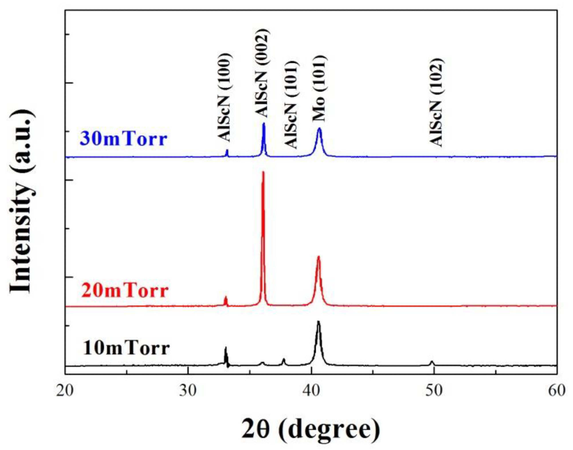
Figure 4. XRD diffraction patterns of AlScN films deposited at different sputtering pressures. Image Credit: Coatings 2021
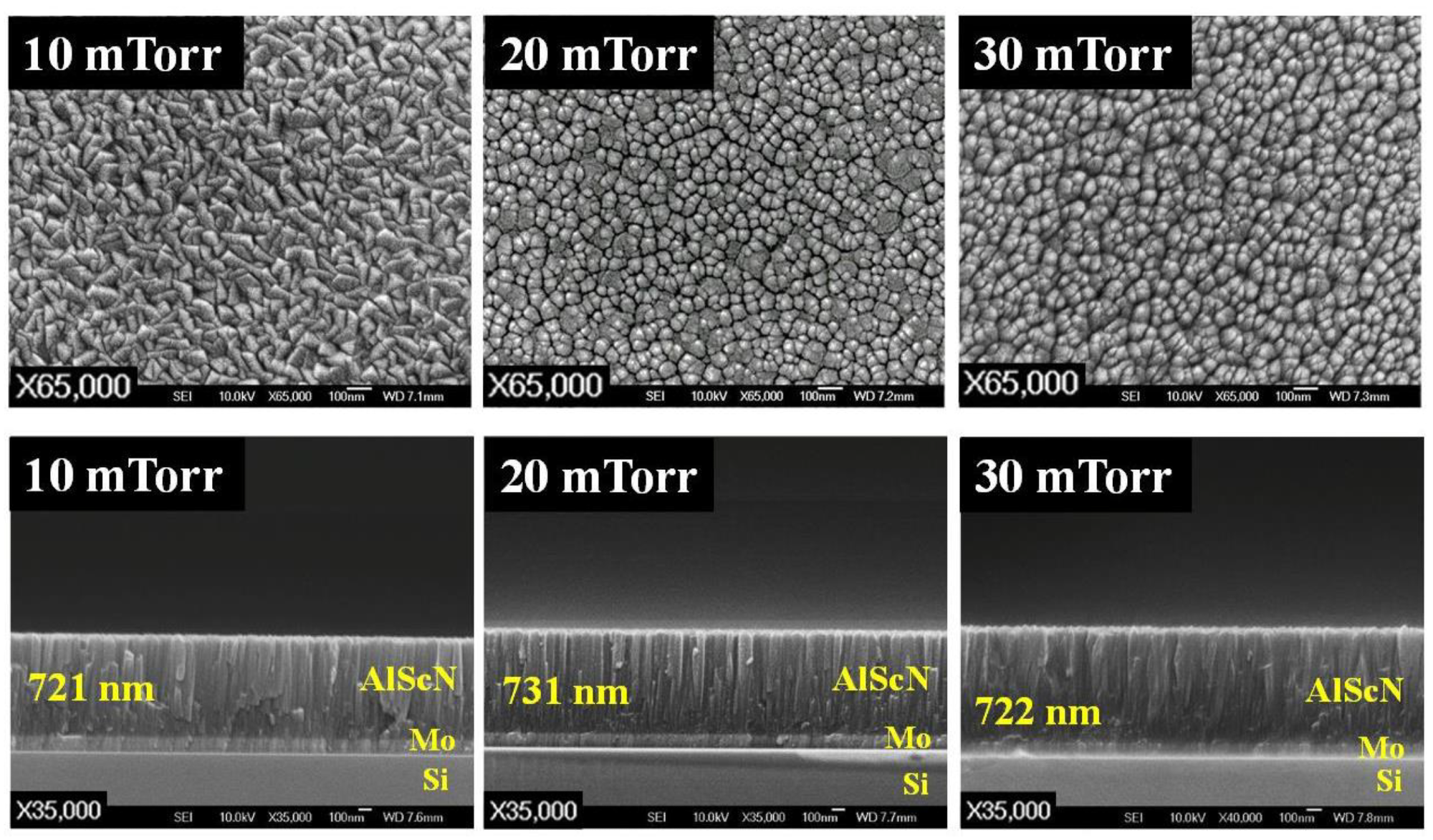
Figure 5. SEM images of the surfaces and cross-sectional structures of AlScN films deposited at different sputtering pressure. Image Credit: Coatings 2021
The influence of the gas environment on the AlScN film was verified. Figure 6 shows that the film exhibits the strongest intensity of (002) crystal orientation at a nitrogen ratio of 20%, then decreases with the increased nitrogen ratio.
Figure 7 illustrates that the surface of the film sputtered at the nitrogen ratio of 20 mTorr exhibits a dense cobblestone structure and an excellent columnar cross-section.
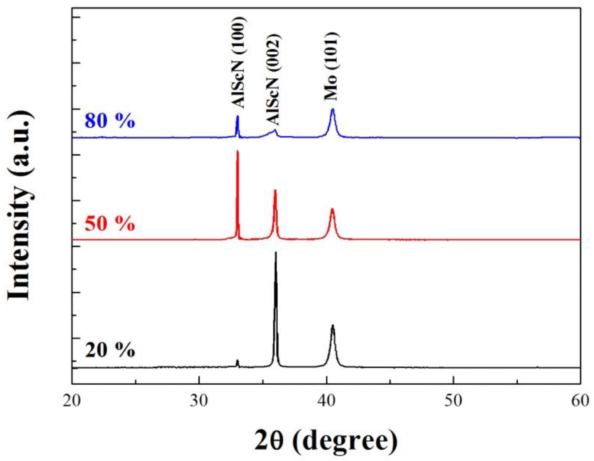
Figure 6. XRD diffraction patterns of AlScN films deposited at different sputtering nitrogen ratios (N2/N2 + Ar). Image Credit: Coatings 2021
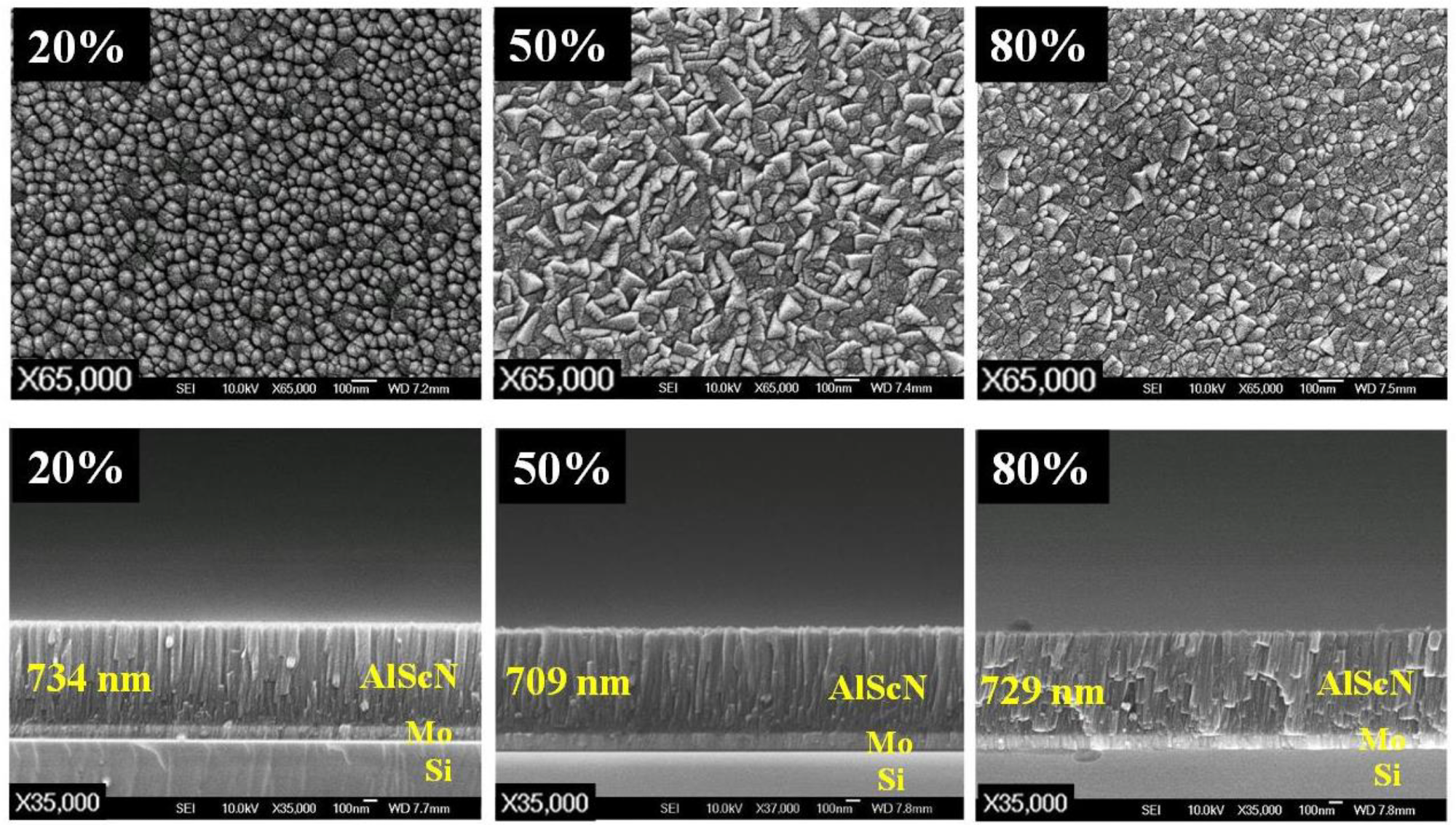
Figure 7. SEM images of the surfaces and cross-sectional structures of deposited AlScN films at different nitrogen ratio (N2/N2 + Ar). Image Credit: Coatings 2021
The sputtering pressure, nitrogen ratio, and substrate temperature were modified and the parameters were verified again. Figure 8 shows an increase in the sputtering power that makes the film exhibit the strongest (002) crystal orientation.
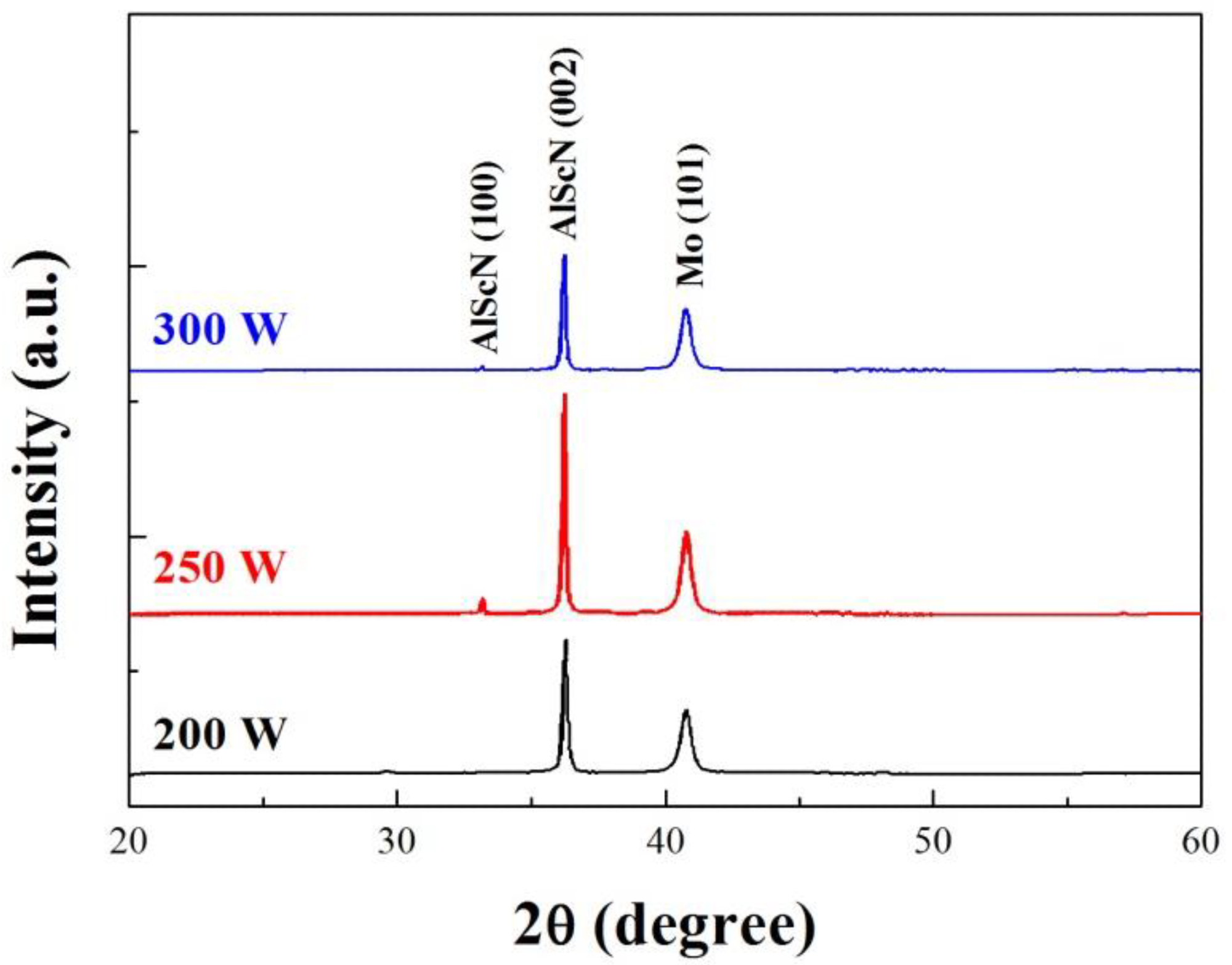
Figure 8. XRD diffraction patterns of AlScN films deposited at different sputtering power. Image Credit: Coatings 2021
Figure 9 depicts the SEM images of the surfaces and cross-sectional structures of the AlScN films deposited under different sputtering powers.
The above results indicate that a chamber pressure of 20 mTorr, nitrogen ratio of 20%, substrate temperature of 300 °C, and sputtering power of 250 W are the optimal parameters to deposit the AlScN films.
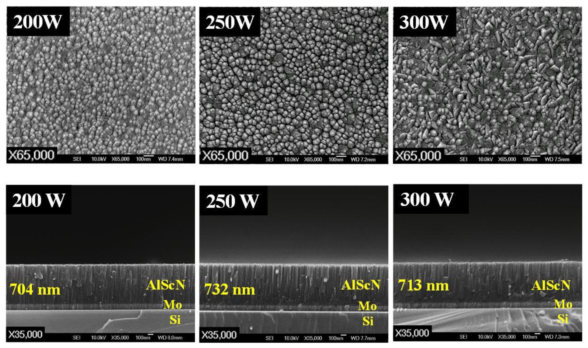
Figure 9. SEM images of the surfaces and cross-sectional structures of AlScN films deposited at different sputtering power. Image Credit: Coatings 2021
The compositions of the AlScN films were analyzed by EDS under various sputtering conditions.
The results show that the scandium content in the film under different sputtering pressures, nitrogen ratios, and sputtering powers is not much different. The overall results show that the percentage of scandium atoms in the film is about 4.5%.
Bragg reflectors with three pairs of Mo/SiO2 were used in the SMR devices.
To verify the effect of Sc doping in AlN piezoelectric film on the characteristics of acoustic wave devices, a 3.5 GHz SMR device with an AlN piezoelectric film was fabricated. Figure 10a illustrates the S21 response of the AlN-based SMR.
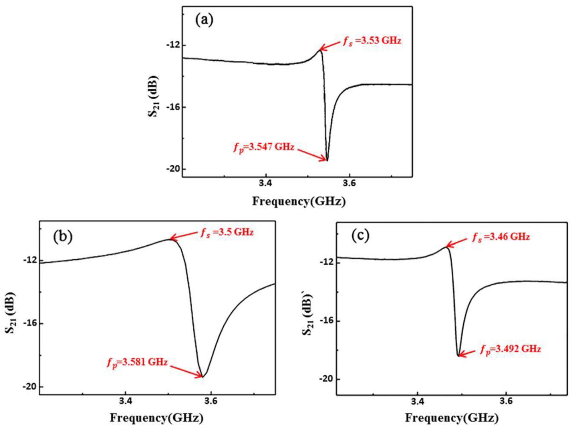
Figure 10. Frequency responses (S21) of SMR resonators using AlScN and AlN as piezoelectric layers, (a) experimental results of AlN-based resonator, (b) simulation results of AlScN-based resonator, and (c) experimental results of AlScN-based resonator. Image Credit: Coatings 2021
The SMR device was fabricated by adjusting the thickness of the piezoelectric AlScN thin film according to the λ/2 mode SMR design.
The simulated frequency response of S21 is illustrated in Figure 10b. It can be seen that a resonance response with a frequency of 2.97 GHz is obtained.
Figure 10c depicts the frequency response of S21 of the SMR device after adjusting the thickness of the piezoelectric layer.
Figure 11 shows the frequency response S11 of the SMR device with the 731-nm-thick AlScN piezoelectric film. A return loss of −30.62 dB is also shown in Figure 11.
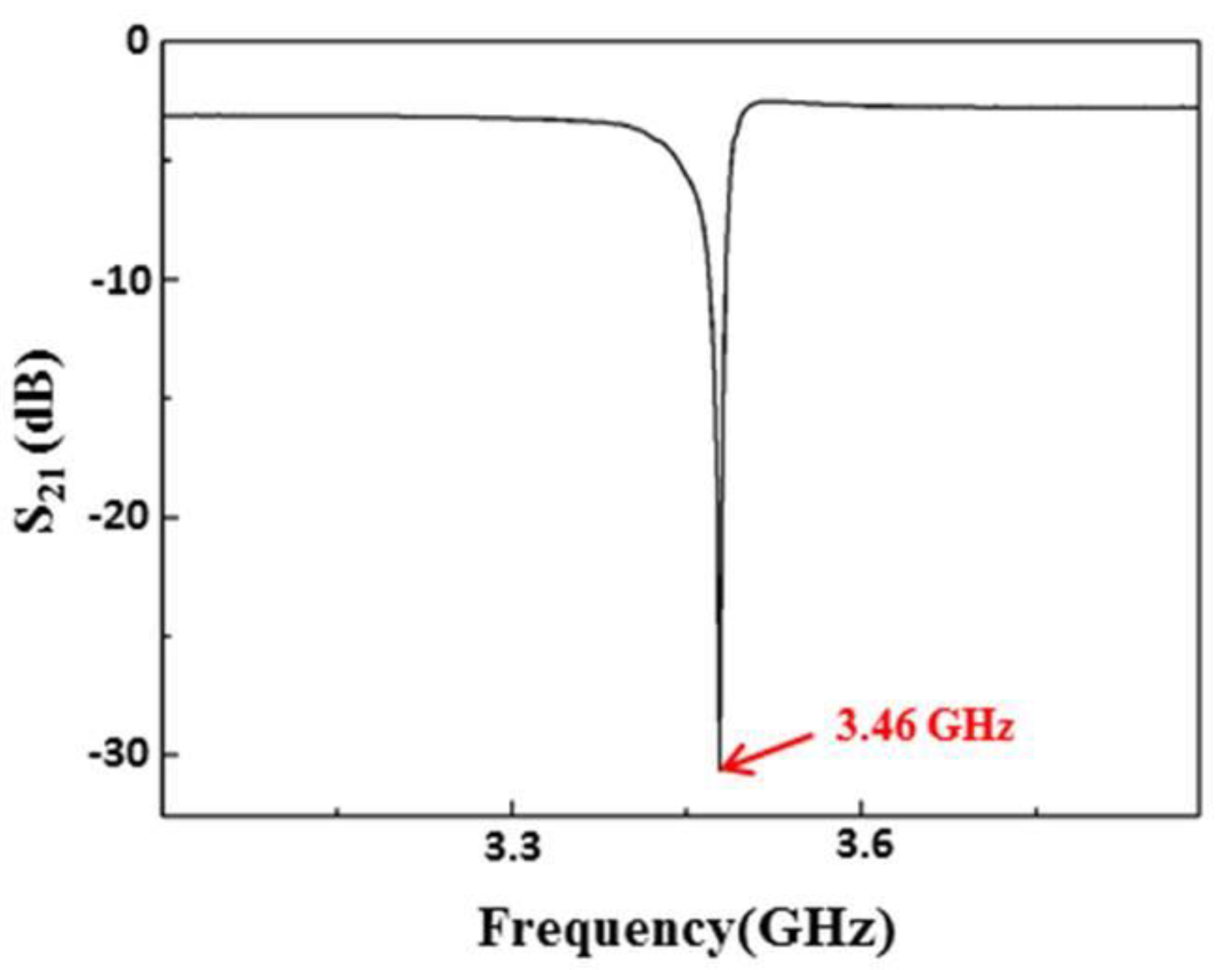
Figure 11. The frequency response S11 of the fabricated SMR resonator. Image Credit: Coatings 2021
In the 3.5-GHz SMR devices made of AlN and AlScN, the insertion loss of the two components is not much different.
RF magnetron sputtering system was successfully used to control the thickness of AlScN film at 731 nm, obtaining the designed 3.5 GHz SMR devices. Figure 12 illustrates the cross-section of the final fabricated device.
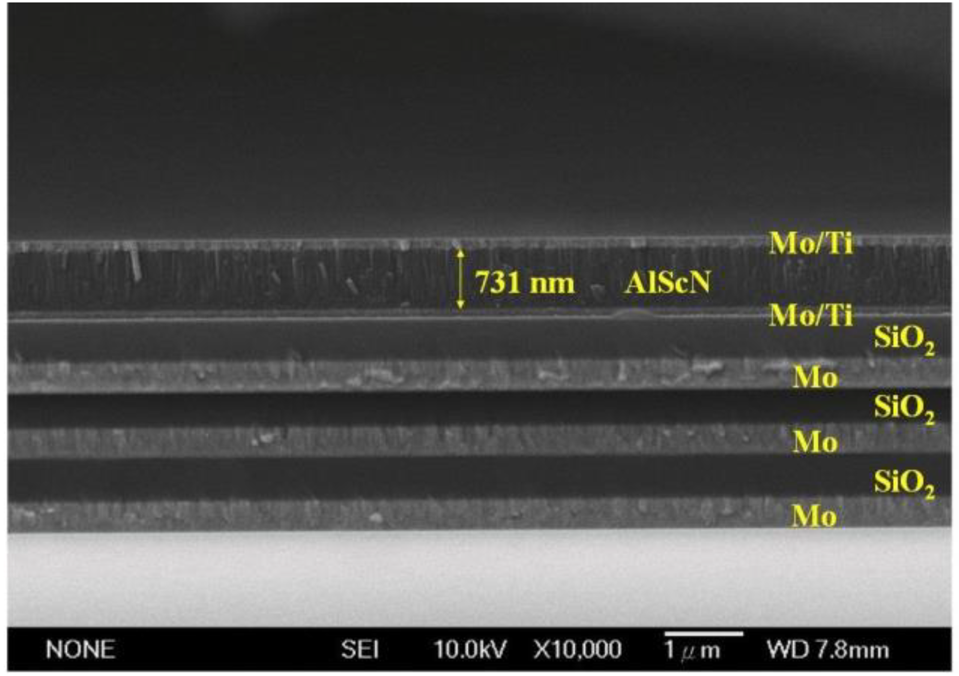
Figure 12. SEM cross-sectional structure diagram of the SMR device. Image Credit: Coatings 2021
Conclusions
The experimental results show that the doping of Sc in the AlN film changes the film’s sound velocity and significantly increases its elastic constant, thereby increasing the electromechanical coupling coefficient of the SMR device.
An excellent c-axis (002) crystalline orientation with a dense columnar and pebble-like surface was achieved.
The EDX analysis showed that the percentage of scandium atom in the film is about 4.5%, regardless of the sputtering conditions.
The fabricated resonator exhibited a resonance frequency of 3.46 GHz, the insertion loss was −10.92 dB, and the electromechanical coupling coefficient was 2.24%.
According to the obtained results, the electromechanical coupling coefficient of the AlN-based device was 1.17% and that of the AlScN-based device was 2.24%.
The effect of Sc-doped AlScN piezoelectric film was verified. The electromechanical coupling coefficient can be further increased by using alloy targets with a higher atomic ratio of Sc or through co-sputtering technology.
References and Further Reading
Akiyama, M., et al. (2009) Enhancement of piezoelectric response in scandium aluminum nitride alloy thin films prepared by dual reactive cosputtering. Advanced Materials, 21, pp. 593–596. doi.org/10.1002/adma.200802611.
Alsaad, A & Ahmad, A (2006) Piezoelectricity of ordered (ScxGa1–xN) alloys from first principles. The European Physical Journal B, 54, pp. 151–156. doi.org/10.1140/epjb/e2006-00438-8.
Awang, Z., et al. (1996) Sol-Gel Derived Bulk Acoustic Wave Devices For Cellular Communication Applications. Proceedings of the IEEE International Conference on Semiconductor Electronics, Volume 1, pp. 238–243. doi.org/10.1109/SMELEC.1996.616490.
Chung, Chan-Yu, Ying-Chung Chen, Yu-Cheng Chen, Kuo-Sheng Kao, and Yu-Chen Chang. (2021). "Fabrication of a 3.5-GHz Solidly Mounted Resonator by Using an AlScN Piezoelectric Thin Film" Coatings 11, no. 10: 1151. https://doi.org/10.3390/coatings11101151
Dubois, M.-A., et al. (1998) Solidly Mounted Resonator Based on Aluminum Nitride Thin Film. Proceedings of the 1998 IEEE Ultrasonics Symposium, Volume 1, pp. 909–912. doi.org/10.1109/ULTSYM.1998.762291.
Farrer, N & Bellaiche, L (2002) Properties of hexagonal ScN versus wurtzite GaN and InN. Physical Review B, 66, pp. 201–203. doi.org/10.1103/PhysRevB.66.201203.
Hara, M & Esashi, M (2004) RF MEMS and MEMS Packaging. Proceedings of the International Symposium on Acoustic Wave Devices for Future Mobile Communication Systems, pp. 115–122.
Huang, C.-L., et al. (2005) Fabrication and performance analysis of film bulk acoustic wave resonators. Materials Letters, 59, pp. 1012–1016. doi.org/10.1016/j.matlet.2004.11.047.
Jakkaraju, R., et al. (2003) Integrated approach to electrode and AlN depositions for bulk acoustic wave (BAW) devices. Microelectronic Engineering, 70, pp. 566–570. doi.org/10.1016/S0167-9317(03)00386-1.
Kim, H. H., et al. (2001) A noble suspended type thin film resonator (STFR) using the SOI technology. Sensors and Actuators A: Physical, 89, pp. 255–258. doi.org/10.1016/S0924-4247(00)00551-3.
Kim, S., et al. (2001) AlN-based film bulk acoustic resonator devices with W/SiO multilayers reflector for rf bandpass filter application. Journal of Vacuum Science and Technology B - Nanometer Struct, 19, pp. 1164–1169. doi.org/10.1116/1.1385685.
Kim, S.-H., et al. (2000) Bragg Reflector Thin Film Resonator Using Aluminium Nitride Deposited by RF Sputtering. Proceedings of the Asia-Pacific Microwave Conference, pp. 1535–11538. doi.org/10.1109/APMC.2000.926131.
Kirby, P., et al. (2003) Thin film piezoelectric property considerations for surface acoustic wave and thin film bulk acoustic resonators. Journal of the European Ceramic Society, 23, pp. 2689–2692. doi.org/10.1016/S0955-2219(03)00147-X.
Lakin, K (2005) Thin film resonator technology. Proceedings of the IEEE International Frequency Control Symposium, pp. 765–778. doi.org/10.1109/TUFFC.2005.1503959.
Lakin, K M (1999). Thin film resonators and filters. Proceedings of the 1999 IEEE Ultrasonics Symposium, Volume 2, pp. 895–906. doi.org/10.1109/ULTSYM.1999.849135.
Lakin, K. M., et al. (2002) Bulk acoustic wave resonators and filters for 2GHz. Proceedings of the IEEE MTT-S, pp. 1487–1490. doi.org/10.1109/MWSYM.2002.1012137.
Lakin, K., et al. (1995) Development of miniature filters for wireless applications. IEEE Transactions on Microwave Theory and Techniques, 43, pp. 2933–2939. doi.org/10.1109/22.475658.
Lanz, R., et al. (2001) Solidly Mounted BAW Filters for the 6 to 8 GHz Range Based on AlN Thin Films. Proceedings of the 2001 IEEE Ultrasonics Symposium, Volume 1, pp. 843–846. doi.org/10.1109/ULTSYM.2001.991851.
Lanz, R., et al. (2002) Surface Micromachined BAW Resonators Based on AlN. Proceedings of the IEEE Ultrasonics Symposium, Volume 1, pp. 981–983. doi.org/10.1109/ULTSYM.2002.1193560.
Larson, J., et al. (2000) Modified butterworth-van dyke circuit for FBAR resonators and automated measurement system. Proceedings of the 2000 IEEE Ultrasonics Symposium, Volume 1, pp. 863–868. doi.org/10.1109/ULTSYM.2000.922679.
Lee, S., et al. (2003) Growth of highly c-axis textured AlN films on Mo electrodes for film bulk acoustic wave resonators. Journal of Vacuum Science & Technology A Vac. Surf. Film, 21, pp. 1–5. doi.org/10.1116/1.1521961.
Lee, S.-H., et al. (2002) Influence of electrode configurations on the quality factor and piezoelectric coupling constant of solidly mounted bulk acoustic wave resonators. Journal of Applied Physics, 92, pp. 4062–4069. doi.org/10.1063/1.1505977.
Loebl, H., et al. (2002) Solidly mounted bulk acoustic wave filters for the GHz frequency range. Proceedings of the 2002 IEEE Ultrasonics Symposium, Volume 1, pp. 919–923. doi.org/10.1109/ULTSYM.2002.1193546.
Loebl, H., et al. (2004) RF bulk acoustic wave resonators and filters. Journal of Electroceramics, 12, pp. 109–118. doi.org/10.1023/B:JECR.0000034005.21609.91.
Mattila, T., et al. (2002) Micromechanical Bulk Acoustic Wave Resonator. Proceedings of the IEEE Ultrasonics Symposium, Volume 1, pp. 945–948. doi.org/10.1109/ULTSYM.2002.1193551.
McCarron, K., et al. (1988) Growth and Characterization of Aluminium Nitride Thin Films for Piezoelectric Devices. Proceedings of the IEEE Ultrasonics Symposium, pp. 673–676. doi.org/10.1109/ULTSYM.1988.49462.
Naik, R., et al. (2000) Measurements of the bulk, C-axis electromechanical coupling constant as a function of AlN film quality. IEEE Transactions on Ultrasonics, Ferroelectrics, and Frequency Control, 47, pp. 292–296. doi.org/10.1109/58.818773.
Newell, W (1965) Face-mounted piezoelectric resonators. Proceedings of the IEEE, 53, pp. 575–581. doi.org/10.1109/PROC.1965.3925.
Ntagwirumugara, E., et al. (2007) Analysis of frequency response of IDT/ZnO/Si SAW filter using the coupling of modes model. IEEE Transactions on Ultrasonics, Ferroelectrics, and Frequency Control, 54, pp. 2011–2015. doi.org/10.1109/TUFFC.2007.495.
Pinkett, S., et al. (2002) Broadband Characterization of Zinc Oxide-Based Solidly Mounted Resonators. Proceedings of the 2002 IEEE International Frequency Control Symposium and PDA Exhibition, pp. 15–19. https://doi.org/10.1109/FREQ.2002.1075849.
Tasnádi, F., et al. (2010) Origin of the anomalous piezoelectric response in wurtzite ScxAl1−xN alloys. Physical Review Letters, 104, pp. 137601–137604. doi.org/10.1103/PhysRevLett.104.137601.
Tay, K.-W., et al. (2004) Performance characterization of thin AlN films deposited on Mo electrode for thin-film bulk acoustic-wave resonators. Japanese Journal of Applied Physics, 43, pp. 5510–5515. https://doi.org/10.1143/JJAP.43.5510.
Turner, R., et al. (1994) Materials for high temperature acoustic and vibration sensors: A review. Applied Acoustics, 41, pp. 299–3244. doi.org/10.1016/0003-682X(94)90091-4.
Wang, W., et al. (2014) High performance AlScN thin film-based surface acoustic wave devices with large electromechanical coupling coefficient. Applied Physics Letters, 105, pp. 133–502. doi.org/10.1063/1.4896853.