| For many years, carburising has been amongst the most widely used processes for developing a hard, wear resistant layer on steel components. Fluidised bed furnaces have proven themselves to be very effective in carrying out the carburising process. Whilst conventional atmosphere carburising can be carried out in the fluidised bed, the boost/diffuse technique is the preferred option, with cycles carried out between 920°C and 1000°C. During the boost period, enriching hydrocarbon gas in excess of the desired carbon potential is passed through the furnace. This enriching hydrocarbon is generally natural gas or propane and is mixed with a carrier gas such as nitrogen to dilute the hydrocarbon, Following this boost period in which the surface of the material is saturated with carbon, the component then undergoes the diffuse period, whereby only nitrogen is present and the absorbed carbon diffuses towards the core of the material. The rate of carbon absorption is controlled by the carbon potential present in the furnace, as well as the surface activity and solubility limit of the steel, whilst diffusion is controlled by Ficks Law. As with vacuum and plasma carburising the surface carbon and effective case depth can be calculated by a computer program to give optimum times. Advantages of Using a Fluidised Bed Furnace There are a number of advantages gained by using fluidised beds. The major difference between carburising in fluid beds and conventional furnaces is the extremely high carbon potentials produced in the fluid bed during the boost period. Research has shown that within minutes of passing the hydrocarbon gas into the furnace it has broken down to produce free carbon particles causing the bed to reach a high carbon potential. For this reason treatment times in fluid beds can be significantly shorter than in conventional furnaces. Other advantages of the fluid bed include good temperature uniformity and excellent heat transfer properties which translates to better process control and uniformity. The Importance of Controlling the Carbon Profile However, even with the latest furnace technology, manufacturers are often unsure as to what are optimal case properties. It is clear that the carbon profile is crucial in producing optimal properties and performance on a case hardened component. In fact it is the carbon profile that generally determines the microstructure and hardness profile of the final treated component. For example, if the carbon content at the surface is too low then the resultant hardness and wear resistance will be subsequently poor. Conversely, too high levels of carbon leads to excessive retained austenite and the formation of carbide networks at grain boundaries which can lead to premature fatigue failure. The Hardness Profile and Carbon Gradient What is considered particularly desirable is a relatively high surface hardness that extends into the steel producing what is referred to as a flat hardness profile. This type of hardness profile can provide a number of advantages. Firstly, in comparison with standard hardness profiles, the flatter profile will have higher hardness values at similar depths, and therefore improved wear resistance over the life of the component. Furthermore it has been shown that higher carbon levels can result in small spheroidal carbides forming within grains which have been shown to improve wear resistance. Secondly, a great number of carburised components are machined or ground after case hardening in order to bring them back to within operating tolerances. It is common for up to 0.2 mm of material to be removed from the component in the final machining or grinding process. The problem with this practice is that in typical case depths of up to 1.00mm, this is removing 20% of your hardened zone, and once removed the underlying surface has considerably less carbon and therefore lower hardness and wear resistance. Considering these points it is therefore important to establish the correct ratio between boost and diffuse times to obtain a carbon gradient that will produce the desired transformation sequence and case depths upon quenching. The Pulsed Boost Diffuse Technique Tests have indicated that merely increasing the boost period to obtain higher carbon levels leads to excessive retained austenite and/or carbide networks. There is however, an alternative to the standard carburising cycle, which gives greater control over the final carbon profile. This technique is known as the Pulse Boost Diffuse technique (PBD). The key is to shorten the boost and diffuse periods but repeat them a number of times during the one cycle at the same temperature. This ensures that high levels of carbon are maintained at increased depths, hence producing a flat hardness profile. An additional advantage of this technique is that small spheroidal carbides can nucleate within the microstructure as a result of the higher carbon levels. Case Study – Pulse Diffuse Boost Treating of 9310 Steel A series of experimental trials was therefore conducted to evaluate the effectiveness of the Pulse Boost Diffuse treatment and determine if indeed a superior carbon and hardness profile could be obtained. The sample material was 9310, a commonly used carburising steel and one which can provide difficulties when attempting to achieve higher carbon levels due to the high nickel content (up to 3.55%) acting as a retained austenite stabiliser and causing excessive carbide networking. Experimental Procedure All tests were conducted in a fluidised bed furnace at 950°C using natural gas as the enriching gas and high purity nitrogen as the carrier gas. All samples were machined from 93 10 barstock. Standard Boost and Diffuse Carburising Cycle The first test (cycle 1) involved performing a standard boost and diffuse carburising cycle to obtain an effective case depth of 1.00mm. A computer program based upon the Harris Equation was used to determine the boost and diffuse times. It was calculated that a boost period of 47 minutes was required, followed by a diffuse period of 113 minutes. On completion of the carburising cycle the samples were direct oil quenched followed by a temper at 180°C. Finally, each sample was cryogenically treated in liquid nitrogen to transform any retained austenite and a second temper carried out. This standard cycle was performed not only to evaluate results but also to act as a standard against which the Pulse Boost Diffuse cycles could be compared. Pulse Boost Diffuse Carburising Treatment Cycle The second stage of the experiment was to carry out the Pulse Boost Diffuse treatments. This initially involved dividing up the standard cycle into shorter boost and diffuse periods and repeating these a number of times. The first Pulse Boost Diffuse cycle was 15 minutes boost and 25 minutes diffuse repeated four times, producing a total cycle time the same as the standard cycle. A second FBI) cycle reduced the boost period to 10 minutes and extended the diffuse period to 30 minutes also repeated four times. As with the standard cycle these samples underwent an initial temper followed by subzero treatment and final temper after carburising. It is important to note that the total treatment time was kept constant in order to keep the effective case depth to 1.00mm. All other variables such as quench rates were kept constant. After the trails each specimen was cut, mounted in epoxy resin, etched and the microstructure examined. Finally, each sample underwent a traverse hardness test to determine the hardness profile. This was carried out on a Vickers microhardness tester using a 100g load. A summary of the cycles carried out is given in Table 1. | | | 1 | 950 | 47 | 113 | 1 | Oil | Temper, Subzero, Temper | | 2 | 950 | 15 | 25 | 4 | Oil | Temper, Subzero, Temper | | 3 | 950 | 10 | 30 | 4 | Oil | Temper, Subzero, Temper | Results Plotting hardness versus depth clearly demonstrates the difference between the cycles and ultimately provides an indication of the final carbon profile produced. Graphical representation of results for the various cycles is shown in Figure 1. | 
| | Figure 1. Hardness profiles of 9310 steel after the various carburising treatments. | Hardness Profile for the Boost and Diffuse Treatment
The standard carburising cycle (cycle 1) resulted in a surface hardness of 700HV that begins to taper off after only 100 microns down to a core hardness of 380HV The effective case depth was approximately 0.9mm (determined at 500Hv. The microstructure for the standard cycle was predominantly tempered martensite with a very few scattered carbides. Hardness Profile for the Pulse Boost Diffuse Treatment The hardness profiles produced by the two Pulse Boost Diffuse cycles were similar, however both of which were considerably different to that produced by the standard cycle. Both cycle 2 and cycle 3 had a high surface hardness (760Hv) as compared to the standard treatment. This higher hardness has been maintained to a depth of 0.3mm hence producing a flat hardness profile, At approximately 0.8mm all three profiles come together to give an effective case depth of between 0.9mm and 1.00mm. In all cases core hardness was between 360 and 400HV. Microstructural Differences The main difference between the two Pulse Boost Diffuse cycles was in the case microstructure. In both cases the matrix was composed of tempered martensite, but cycle 2 produced a microstructure with strong grain boundary carbide networks. Cycle 3 however, produced a marked improvement in microstructure. Although some large carbides are present, they are evenly dispersed and there is no carbide networking at grain boundaries. Figure 2 indicates the microstructures produced by each cycle. | 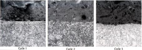
| | Figure 2. Microstructures of 9310 steel after the various carburising treatments. | Discussion Modifications to the standard carburising cycle in order to alter carbon levels and nucleate spherical carbides is not new technology. In fact, carbide dispersed carburising was first proposed by O.E. Cullen in 1961, and has been covered in a number of papers since. However, these methods have required that a second furnace be available in order to nucleate carbides at a lower temperature once the boost period is complete. This technique, whilst successful in producing higher hardness values and intergranular carbides, is not practical in the heat treatment industry. Therefore, a major advantage of the Pulse Boost Diffuse cycle is that it can be carried out in a single furnace at one temperature without interruption, and with modern programmable controllers the cycle can be carried out with a minimum of supervision. Effect of Treatment Cycle on Hardness In comparing the results obtained from the experiments, it is clear that the Pulse Boost Diffuse technique has the capability to produce a superior carbon profile, and subsequently an improved hardness profile. This is illustrated in Figure 1, as both cycle 2 and cycle 3 have achieved a greater surface hardness and a considerably flatter profile whereby hardness has been maintained at increased depths. In fact the Pulse Boost Diffuse cycles have both maintained 700HV or above, up to 0.3mm within the case. This type of profile would provide excellent wear resistance on the component and extend service life considerably. It would also mean that any grinding or machining after carburising would have less of a detrimental effect on the case. It should be noted that the effective case depths produced by all three cycles were very similar, and beyond 0.7mm all hardness values are approximately the same. This means the Pulse Boost Diffuse cycle can be carried out without having to extend standard treatment times, and that controlled case depths can be achieved on critical components. The Effect of Microstructure on Materials Properties The effect of microstructure on the final properties of 9310 is also of considerable importance. Again the microstructure is strongly dependant on carbon content and achieving an optimum gradient. Lower levels of carbon are not easily detectable, but will result in reduced hardenability and wear resistance. Excessive carbon has a much more pronounced effect. Excessive carbon can firstly lead to unacceptable levels of retained austenite. In the trials conducted all samples were subjected to a subzero treatment in order to minimise retained austenite, but the effects of retained austenite must be considered. Retained austenite is generally not considered harmful when present in amounts less than 30%, particularly if finely dispersed, and in some instances a small amount of retained austenite is desirable. However, in other applications such as heavily loaded gears, retained austenite is limited to less than 5%, given that austenite is unstable and can cause lower hardness, reduced wear resistance and premature failure. Excessive Carbon Excessive carbon has the additional problem of creating grain boundary carbides. As carbon levels increase, carbides begin to outline prior austenite grain boundaries. If these levels continue to increase the carbides will not only grow in size but network along the grain boundaries. Large particle carbide precipitates at grain boundaries are detrimental to impact toughness and contact fatigue properties. This situation has occurred in cycle 2 and it appears that the longer boost periods have lead to an acceptable carbon level. It is likely that a component with this microstructure would fail in service. It should also be noted that 9310’s high concentration of nickel acts as a carbide stabiliser, and is the likely reason that carbides were present in all cycles conducted. An additional factor to consider is the concept of the corner effect. Most components have a sharp edge of some description, which can also enhance the problem of having excessive carbon levels as a result of carbon diffusing from both sides of the corner. However, in sensitive components where this may pose problems copper plating or stop off paints may be utilised to minimise the problem. Controlled Carbide Formation Controlled carbide formation, can however, provide benefits. The volume, size and distribution of carbides in a case microstructure all have a distinct influence on wear resistance. Generally, wear resistance improves as the volume of carbides increase at the wear surface due to the very high hardness levels obtained by alloy carbides. It is therefore important to be able to produce finely dispersed carbides within the microstructure of a case hardened component, such as those produced by cycle 3. Summary Carburising in a fluid bed furnace offers a number of advantages over conventional carburising furnaces. The ability to operate at higher carbon potentials as well as excellent temperature uniformity and heat transfer properties means improved process control. It is clear that by altering the carburising cycle to produce an optimum carbon profile the final properties of a case hardened component can be significantly improved. This has been illustrated with the Pulse Boost Diffuse (PBD) technique, which has succeeded in maintaining higher carbon levels in the case of the steel, and therefore providing considerable improvement in the hardness profile and microstructure. It is recommended that further optimisation of the PBD process be carried out to further quantify the benefits of this process. |