Sponsored by GGBJan 14 2022
Polymer bearings incorporating a PTFE-based running surface were viewed as a step forward in scroll compressor performance when they were initially introduced around three decades ago.
These polymer bearings are comprised of a polymer surface layer, a porous bronze interlayer and a steel supporting layer. This composition has grown to be prevalent in compressor applications, with continued improvements in bearing composition and performance and consequently improved environmental impact.
The application of the polymer to the bronze bearing interlayer has usually depended on the deposition of a composite slurry to create a surface that is low friction and wear-resistant.
This method of deposition has served the compressor application well, but the inherent nature of the slurry-based process meant that the lifespan of the bearing was essentially restricted by the integrity of the polymer integrity and thickness of the polymer layer.
Recent advancements have seen the development of new material technology in the scroll compressor sector. This allows bearing manufacturers to offer improvements in terms of durability and seizure resistance compared to the traditional methods of slurry-based deposition.
The resulting improvements in performance have been evidenced by means of comprehensive tribological testing in general tribological testing conditions and techniques pertinent to scroll compressor conditions.
This article outlines an assessment of bearing materials produced by multiple process technologies as well as outlining tribological results recording performance enhancement.
The test data shown includes findings from bearing development and manufacture, as well as qualification tests performed by a leading manufacturer of compressors, detailing advances in bearing durability and seizure resistance.
The successful utilization of multilayer PTFE-lined bearing materials has occurred in a wide application base. The main reason for this is the filled-PTFE running surface providing self-lubricating properties that outstrip other methods available.
The polymer’s innate low friction properties have facilitated increased efficiency where applications are affected by sliding friction and has led to reductions in wear in systems where bearings are vulnerable to adhesive wear.
The traditional three-layer configuration for polymer bearings type consists of a porous bronze inner layer that has been sintered to a steel backing and impregnated with a filled-PTFE compound. This purposely allows a film of the same composition to remain on top (Figure 1 and Figure 2).
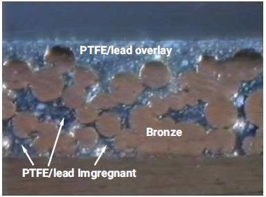
Figure 1. Cross-sectional image showing the multi-layered bearing construction. Image shows a bearing of PTFE/lead composition, the original bearing of this type utilized in scroll compressors. Image Credit: GGB
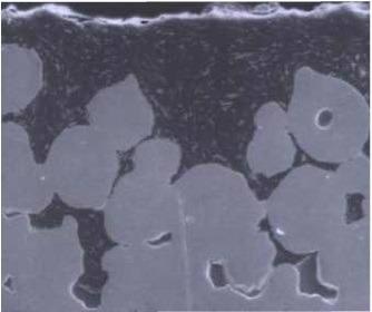
Figure 2. Cross-sectional image of a lead-free composition with MoS2 filler. Image Credit: GGB
Known as the overlay or upper layer, it is a vital element of bearing operation. A number of options are available in terms of composition:
- The bearing may comprise of a PTFE and lead composition - the original multilayer polymer bearing innovation in scroll compressors (Figure 1)
- A lead-free version that has grown in use in various applications in order to adhere to increased environmental standards.
The established manufacturing approach involved the co-coagulation of a PTFE-based aqueous dispersion that possesses the desired particulate fillers. This allows for the creation of a slurry-based compound that can be introduced into the porous bronze structure.1,2
Further advances in the process have led to the development of a dry powder process that - along with compositional improvements - enhanced fatigue and cavitation resistance.3
Modifications in size (post-installation) in powder-based or slurry-based liner methods are restricted to burnishing for both materials. The powder-based liner has been shown to be able to go through significant modification through burnishing while preserving tribological performance.
It is important to note that resizing via machining for either method led to a decreased working life for the bearing and greater friction due to the increased exposure of the bronze interlayer.
The most recent advance in the production of PTFE-based tribological layers has been a result of the process of impregnating higher-integrity polymer films.5,6 Possessing the ability to build a thicker polymer overlay, these films provide improved resistance to crucial tribological conditions such as cavitation erosion and sliding wear.
Traditionally, overlay thickness was usually in the range of 5 to 25 μm (Figure 3 shows an example with a layer of 17 μm). The enhanced overlay form is ostensibly over 100 μm thickness (Figure 4 displays a layer with a thickness of 126 μm).
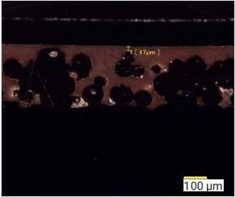
Figure 3. Cross-sectional of historical bearing construction showing limited polymer overlay thickness, in this case, 17 μm. Image Credit: GGB
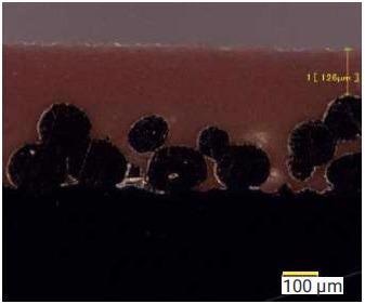
Figure 4. Bearing construction showing machineable polymer overlay, in this case, 126 μm. Image Credit: GGB
A thicker overlay neutralized the sizing limitations of its predecessors, allowing machining after bearing installation to reach a level of precision comparable to that of metallic materials. It also allowed for favorable tribological advancements in a range of conditions central to the operation of scroll compressors.
Experimental Procedure
Materials Tested
Each material subjected to testing involved a traditional composite structure comprised of a metal and polymer combination.
This combination consisted of a steel backing and porous bronze interlayer, as well as a PTFE-based polymer impregnant - within the porous structure with a polymer overlay - as the preliminary running surface.
A total of three individual materials were tested, these were:
- Product DP10™, which is a slurry-based PTFE layer: MoS2 particulate filler, balance PTFE (cross-section shown in Figure 2)
- Product DP31™, which is a powder-based PTFE layer: CaF2, a second fluoropolymer addition and colloidal Al2O3 particulate addition, balance PTFE (cross-section shown in Figure 3)3
- Product DTS10™, a film-based PTFE layer: CaF2, balance PTFE (cross-section shown in Figure 4)5,6
It is important to note that the powder and slurry-based polymer layers were manufactured with a polymer overlay of approximately 25 um, intended for utilization in the as-impregnated state.
In contrast, the film-based PTFE layer was intended to be machined, and as a result, contain a polymer layer of 100 μm or more.
The differences in the overlay can be seen in the cross-section images of the various materials. Performance data is presented in the asformed bearing condition, without any secondary sizing operations being carried out.
Test Methods
Two series of tribological evaluations were carried out, one by GGB (a bearing manufacturer) the other by Daikin Industries, Ltd (a compressor manufacturer). Test descriptions and results are identified as being performed by either tester.
Bearing Manufacturer Test Conditions
Cavitation Erosion
Tests were carried out on flat samples of composite, polymer-lined discs by means of a cavitation test rig (Figure 5). Test samples were held in place magnetically at a position 1 mm below a high-frequency sonic horn (as shown) and immersed in water that was maintained at room temperature.
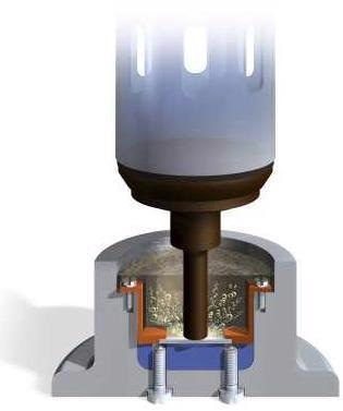
Figure 5. Cavitation erosion rig. Image Credit: GGB
The horn was operated at a frequency of 26 kHz for a length of time that was pre-determined by the material being tested. Any resulting loss of material was measured by weighing samples before and after the test, with the data recorded as an erosion rate in mg per minute.
Boundary Lubricated Wear Testing
Wear testing was carried out on a rig utilizing flat samples of the polymer-lined discs as test samples (Figure 6). The test head comprised three hemispherical counter bodies, known as shoes, that were held in a rotating fixture and compelled to slide against the flat test specimen (Figure 2).
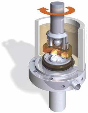
Figure 6. Wear test rig showing the three “shoe“ test configuration. Image Credit: GGB
The lubrication regime was changed from a boundary lubrication format – material to material contact, to a hydrodynamic film – no material contact – depending on temperature, load, speed and oil type (Table 1).
Table 1. Wear Test Conditions. Source: GGB
| Test Regime |
Load |
Speed |
Lubrication |
Oil |
| Boundary Lubrication |
14.5 MPa |
0.163 m/s |
95 °C |
Type F |
It is important to note that the oil type chosen – a Type F transmission fluid – was selected due to its viscosity and tendency to form a specific type of lubrication regime and not as a requirement to simulate any specific application.
Compressor Manufacturer Analysis
Each of the three materials was also assessed under test conditions deemed relevant to those in a scroll compressor. The conditions outlined in this article assessed both seizure and general wear resistance. The seizure and wear testing regimes utilized a 30 mm ID x 20 mm length bushing configuration.
Table 2. Test Parameters. Source: GGB
| Test Parameters |
Seizure Resistance* |
Wear Resistance |
| Load |
step load to 31 MPa |
5.9 MPa |
| Speed |
11.3 m/s |
0 m/s (10 s) - 2.8 m/s (10 s) |
| Lubricant |
24% FVC68D oil w/ R410A |
24% FVC68D oil w/ R410A |
*Seizure resistance test was stopped at friction coefficient >0.2; temperature >200°C
Results
Cavitation Results: Tribological Data From the Bearing Manufacturer
Cavitation testing was performed on each of the three materials, and any subsequent weight loss was also calculated for each sample grouping, with the data reported as a wear rate – in mg per minute – for each material.
The highest erosion loss was noted to occur in the slurry-based liner, followed by the powder-based material. The film-based liner displayed the lowest level of erosion loss.
For comparison purposes, surface images for examples of each of the three materials at equivalent test duration – 6 minutes – are shown (Figure 7, Figure 8 and Figure 9). The removal of portions of the overlay can be seen in the case of the slurry-based material (Figure 7).
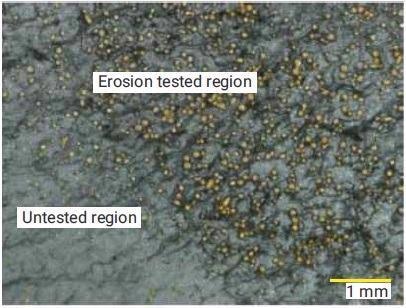
Figure 7. Cavitation erosion test sample, slurry-based liner. Image Credit: GGB
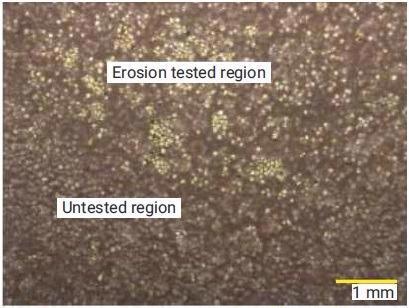
Figure 8. Cavitation erosion test sample, powder-based liner. Image Credit: GGB
The underlying bronze structure can be observed to have become exposed during the cavitation process. The powder-based liner showed decreased exposure of the underlying bronze structure and reduced weight loss rate ( Figure 7 and Figure 10).
The film-based liner’s superior cavitation performance can be both quantified and seen by the surface images (Figure 9 and Figure 10). There was no exposure of the underlying bronze structure due to the lower weight loss rate and the thicker nature of the polymer overlay.
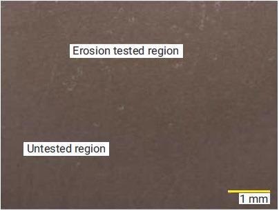
Figure 9. Cavitation erosion test sample, film-based liner. Image Credit: GGB
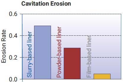
Figure 10. Cavitation erosion data. Image Credit: GGB
Boundary Lubricated Surface Wear
Lubricated wear testing was also carried out for each sample material by utilizing the three ‘shoe’ test rig (Figure 6). The data is presented as wear rate, that is, wear depth (μm) as a function of sliding distance (km) (Figure 14).
Surface images of each material can be seen, displaying the relevant surface appearance after a wear test (Figure 11, Figure 12 and Figure 13).
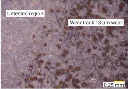
Figure 11. Boundary wear tested sample, slurry-based liner. Image Credit: GGB
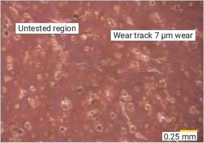
Figure 12. Boundary wear tested sample, powder-based liner. Image Credit: GGB
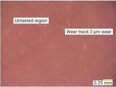
Figure 13. Boundary wear tested sample, film-based liner. Image Credit: GGB
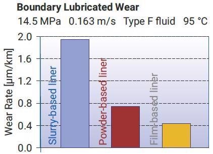
Figure 14. Boundary wear data. Image Credit: GGB
The overall wear depth for each displayed sample is seen in each figure. The results were as follows:
- The wear rate of the slurry-based material was1.9 μm/km
- The wear rate of the powder-based product 0.66 μm/km
- The wear rate of the film-based liner was 0.46 μm/km
The film-based liner’s lower wear rate was in addition to having an overlay thickness of >100 μm. This was noticeably greater than either of the other materials – <25 μm. Greater wear resistance leads to extended bearing life in a compressor, with the thicker overlay – even after machining has occurred – leading to greater durability.
The surface imagery reflected the quantitative wear results, as the material that underwent the greatest wear also displayed the highest wear surface disruption. The surface of a tested slurry-based liner displayed exposure of the underlying bronze layer (Figure 11).
The powder-based liner showed less disruption through wear, visible by only a change in bronze exposure between the untested region and the wear track (Figure 12). The film-based material presented as smooth in comparison with only minor disruption following wear testing (Figure 13).
Boundary Lubricated Friction Data
Both the film-based and powder-based materials display one curve, as the materials normally present with minimal wear in these test conditions. The slurry-based material, by comparison, displayed two friction curves, showing different test responses (Figure 15).
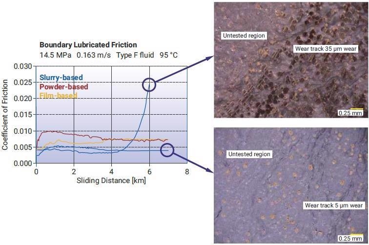
Figure 15. (left) Friction curves from boundary lubricated wear testing. Figures 16 (top right) and 17 (bottom right) showing surface condition after wear testing for a range of bronze interlayer exposure and varied friction results. Image Credit: GGB
The friction curves for the powder-based and film-based materials show that friction was initially higher for those in comparison to the slurry-based liner but experienced low wear and thus consistent friction.
The low wear rate led to minimal exposure of the bronze interlayer at the point of test completion when the final conditions of the powder and film-based samples were examined (Figure 12 and Figure 13).
One slurry-based sample displayed higher wear and resulting bronze exposure which led to increased friction late in the test, with two slurry-based samples showing varying levels of bronze exposure (Figure 16 and Figure 17).
The difference is indicative of the friction increase resulting from bronze exposure in comparison to the friction of a primarily PTFE-based surface.
Tribological Data from the Compressor Manufacturer
The tests were performed to assess the seizure and wear resistance of the three bearing materials.
The wear data obtained by the compressor manufacturer displayed the same order and relative scale of the wear data as that obtained by the bearing manufacturer, though each material was tested under markedly different conditions (Figure 14, Figure 18).
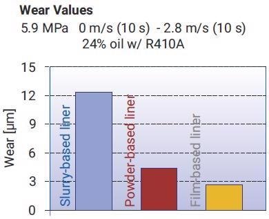
Figure 18. Wear data for compressor manufacturer testing presented as overall wear depth. Image Credit: GGB
Tests by the compressor manufacturer showed that the film-based material had the lowest wear rate, while the slurry-based material had the highest.
Seizure resistance data - presented as the load at which the friction exceeded 0.2 or the temperature exceeded 200 °C - displayed a similar trend as cavitation and wear data with the film-based material exhibiting the most positive performance (Figure 19).
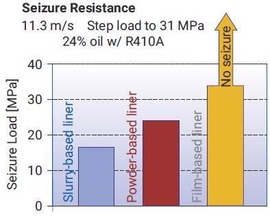
Figure 19. Seizure resistance presented as seizure load. Note that the film-based liner did not seize at the maximum test load. Image Credit: GGB
This data helped to validate the test results discussed above, with the film-based liner exhibiting the highest wear resistance. It is also believed that the low and consistent friction over an extended test duration provided the favorable seizure resistance, especially for the film-based bearing material.
Performance Summary
Tribological data was obtained which compared bearing materials with a range of differences, including:
- The manufacturing method of the polymer wear layer
- Composition of the polymer wear layer
- Thickness of the polymer wear layer
The differences in wear rate were recorded, incorporating relative differences between the testing performed in different test locations using varied test methods that showed a high degree of correlation.
The film-based material had the lowest wear rate and also possessed the greatest wear layer thickness. It also displayed the lowest cavitation erosion rate and the most favorable seizure resistance.
The powder-based material displayed a better performance than the slurry-based material in both data sets and test regimes. The wear layer was nominally identical for both materials, however.
It can be surmised that the production and application process by which the polymer layer was produced had a significant role in bearing performance. Enhanced performance would result in increased bearing life in scroll compressor applications.
Conclusions
Three PTFE-lined bearing materials characterized by their different polymer processing methods were analyzed for wear, cavitation and seizure resistance. The variations in processing related to the means by which a self-lubricating polymer layer was applied to a supporting porous bronze interlayer.
The three methods analyzed were slurry-based processing, a film-based process and a powder-based method.
The film-based material possessed a thicker polymer overlay in comparison to the other materials. This indicated that precision machining after installation and/or increased wear life due to the greater thickness of the self-lubricating polymer layer offered longer bearing life in a compressor application.
Tribological evaluations were conducted independently of each other by the bearing and compressor manufacturers. Each set of results indicated that the most favorable wear performance was provided by the film-based liner, with the powder-based material offering the second-best performance results.
The film-based polymer liner system demonstrated the highest degree of cavitation resistance, wear resistance and seizure resistance. In comparison, the slurry-based material exhibited the lowest resistance levels in each of the analyzed conditions.
References
- Davies, G., Moisey, P., Johnston, J., Plain bearing with polytetrafluoroethylene-based lining, US Patent 5,911,514 (1999)
- McMeekin, K., Johnston, J., Plain Bearing Structure, US Patent 6,296,392 (2001)
- McMeekin, K., Johnston, J., Bearing Materials, US Patent 6,461,679 (2002)4. Kim, M., Peng, Y.H., Small, C., The Tribological Performance of Self-Lubricating Bearings Following
- Secondary Sizing, Purdue Compressor Conference (2006)
- Kim, M., Marsella, D., Johnston, J., Boreable plain bearing material, US Patent 7,491,353 (2009)
- Marsella, D., Belmahdi, S., Novel Low Friction, Machineable Metal-polymer Bearing for Lubricated Applications (in Fluid Power Systems), National Conference on Fluid Power (2011)
- GGBearing Evaluation Result, Compressor Engineering and Development Group, Daikin Industries, Ltd. (2015)
Acknowledgments
Produced from materials originally authored by Michael Kim, Derek Marsella, and Benoit Sidot from GGB.

This information has been sourced, reviewed and adapted from materials provided by GGB.
For more information on this source, please visit GGB.