Sponsored by GGBJan 14 2022
Composite bearings are employed in a diverse array of industries due to their strength, wear and friction characteristics, as well as their capacity to operate efficiently without the use of external lubrication.
Despite offering the most robust tribological performance, filament wound composite bearings have historically been limited in terms of their dimensional tolerance due to the capabilities of the winding process itself.
To machine composite bearings to tight dimensional tolerances has also historically been limited because these frequently include continuous PTFE fibers prone to fraying and fracturing during the machining process.
New advances in self-lubricating fiber/resin composite bearing technology have resulted in novel fiber constructions able to overcome machining limitations while continuing to offer excellent tribological performance.
This article explores the nature of these machining limitations, highlighting key developments in materials design seeking to overcome these limitations.
Background
Composite bearings have seen regular use in hydropower applications for over 20 years, serving as a lubrication-free alternative to grease. These bearings have consistently demonstrated their ability to improve wear performance and working life versus historically employed bronze bearings.1
The wicket gate location has traditionally represented a challenging bearing condition for composites and other bearing types, though PTFE-containing composite bearings have demonstrated robust tribological performance in both hydropower2 and an array of other aggressive industrial applications.
Good dimensional tolerance and stability are central to the viability of composite bearings in hydropower applications, including the wicket gate location. A means of secondary sizing is usually performed on the bearing bore following the winding and curing process in order to ensure that target dimensional tolerance is achieved.
This has historically been performed on the bearing during the manufacturing process itself.
Dongfang Pumped Hydro Turbine
Dongfang Electrical Company approached GGB in 2016, seeking to acquire technical bearing solutions suitable for a new pump storage facility in JiXi, Anhui province.
In-grid energy storage is vital to the growth of renewable energy because this is key to managing the disparity between the availability of renewable energy availability and peak demand – a disparity that has long been a barrier to the widespread adoption of renewables.
Pumped storage represents the highest volume means of energy storage and is a key tool in meeting China’s ever-increasing electricity demands.
This facility had unique bearing demands. Requirements around tight tolerances have become more commonplace throughout the industry, but this facility required an allowance for eccentric machining of the bearings’ bore following installation.
It was vital that the bearings were able to accommodate a head cover offset, but the nature of final offset would remain unknown until the later stages of construction after the bearings had already been installed. This specific and central requirement necessitated the utmost flexibility in design and manufacture.
A machinable bearing product was developed to meet these demands. This product – a wear-resistant liner designed to be machined by a customer after installation of the bearings – leveraged the beneficial properties of discontinuous PTFE fibers within the thermoplastic fibers to achieve this.
The machinable bearings featured a stable, oversized tribological layer designed to facilitate machining by the customer, allowing them to accommodate their precise dimensional needs on a per-bearing basis.
To accommodate this need for a substantial offset, GGB’s interdisciplinary team of engineers calculated and designed bearings with a tribological layer sized to accommodate the complete range of offset dimensions.
This thicker layer allowed the bearings to be machined by the customer once the bearings had been installed in their respective housings.
Composite Materials Design for Optimum Tribological Performance
One widespread and popular method of composite bearing fabrication leverages continuous, twisted fibers of PTFE and another thermoplastic – for example, polyester – to partly encapsulate or surround the PTFE fibers.
PTFE fibers tend to exhibit unfavorable bonding characteristics, meaning these should ideally be supported within epoxy or another resin matrix. Particulate fillers are occasionally added to a polymer composite resin matrix, for example, graphite,1 PTFE3 or other particulate types.4
Previous research has highlighted the advantages of bearing material design related to wear performance, both in terms of the bearing and the mating shaft material.5
The most common wicket gate conditions are identified and outlined in the US Army Corps of Engineers’ test specification: CERL TR 99/104.2 The test outlined in this guidance features a mix of moderate to high and variable loading (23-30 MPa), and a range of dithering (low angle, high-speed oscillation) and slower, large-angle oscillating test conditions.
In the study presented here, the tribological performance of self-lubricating bearings in a wicket gate application was measured using the US Army Corps of Engineers (COE) Specification CERL TR 99/104.2
This test requires the use of two distinct conditions within the same continuous test to assess bearing performance (Table 1).
Table 1. Test Conditions: US Army COE Specification CERL TR 99/104. Source: GGB
| . |
| Load: |
23 - 30 MPa |
Dithering condition: |
Once every 15 minutes: |
| Bearing size: |
127 mm ID |
+/- 1°
2 Hz |
+/- 15°
0.1 Hz (10 seconds full sweep) |
| Shaft: |
17 - 4 |
| Hardness: |
HRC 40 |
| Roughness: |
Rc: 0.4 µm max |
A previous study into the potential of the bearing type used within this machining study explored its performance in the specified dithering condition.5 Tribological performance in that particular mode was assessed in the presence of a number of shaft counterbody types in comparison to a baseline composite self-lubrication bearing.1
The shaft types evaluated were comprised of thin dense chromium plating, mild steel (1040 grade) and hardened stainless steel (420 grade). It was demonstrated that the baseline composite bearing resulted in the presence of tribo-oxidative wear in both of the steel grades, leading to considerable shaft roughening.
This increase in shaft roughness led to accelerated bearing wear of the polymer-based self-lubricating surface. Figure 1a and Figure 1b highlight these two phenomena: shaft roughening and its related bearing wear.
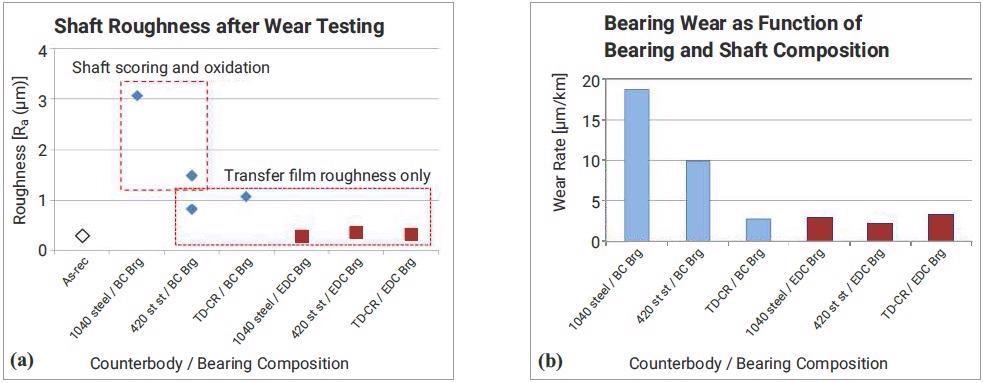
Figure 1. Tribological data showing (a) shaft roughness after wear testing exhibiting difference between baseline composite bearing and an advanced bearing designed for enhanced dithering performance. That bearing was the same on used in this work to investigate machining response. Accompanying bearing wear (b) also displayed. Image Credit: GGB
The PTFE fiber bearing studied exhibited none of these detrimental responses.5 Figure 1a and Figure 1b also highlight this favorable performance, shown in the presented charts as Enhanced Dithering Composite (EDC).
It was noted that shaft roughness did not change significantly for any of the three counterbody types investigated. Bearing wear was also found to be low. It was theorized that the EDC bearing’s formation of a uniform, self-lubricating transfer film led to this favorable tribological performance.
It was also shown that this lubricious transfer film formation helped inhibit tribo-oxidation, eliminating shaft damage and affording the bearing low wear and consistent tribological system performance.
Enhanced fiber technologies have enabled the application of standard machining procedures. While continuous PTFE fibers tend to fracture during machining - partly due to poor bonding to the resin matrix they are embedded within - discontinuous PTFE fibers encased in thermoplastic fibers offer favorable qualities in terms of tribology and machinability.
The bearing described above as Enhanced Dithering Composite will now be described throughout this article as Discontinuous PTFE Fiber Composite.
Composite Materials Design for Machinability
Superior fiber/resin composite bearings developed to ensure good tribological performance are generally fabricated via a combination of self-lubricating mechanisms.
One such method employs a lubricating particulate filler such as graphite,1 polytetrafluoroethylene (PTFE)3 or other types - including multiple lubricating fillers in the same bearing.4
Self-lubricating materials frequently include PTFE fibers to support a reduction in friction and wear. These may also include an extra thermoplastic fiber to improve the structural integrity of the bearing’s wear-resistant layer.1,3,4 The construction of these fibers may also affect the wear-resistant surface’s machining response.
The experiments described here were performed to compare the machining response variation between composite bearings produced with two different fiber types, both of which were fabricated via a filament winding process.
One bearing type employed separate but continuous fibers of thermoplastic and PTFE compositions. These were blended and twisted together to create a uniform fiber bundle. The second bearing type employed a composite fiber construction comprised of discontinuous PTFE fibers in a thermoplastic fiber matrix.
Figure 2 and Figure 3 feature cross-sectional images which showcase these differences in fiber structures. Figure 2b displays a highlighted long, continuous PTFE fiber, while Figure 3b displays several short, discontinuous fibers in larger thermoplastic fibers.
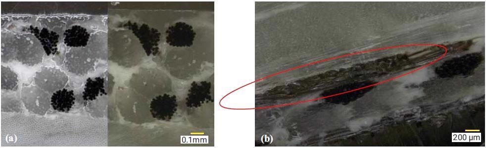
Figure 2. Cross-sectional images showing the continuous PTFE fiber construction. Image (a) shows the fiber structure in transverse view while (b) shows a fiber longitudinally, highlighted by the red oval. Image Credit: GGB
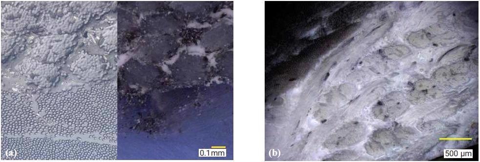
Figure 3. Cross-sectional images showing the discontinuous PTFE fiber construction. Image (a) shows the fiber structure in transverse view while (b) shows fibers longitudinally, highlighted by the red ovals. Image Credit: GGB
The continuous and discontinuous PTFE fiber types were each found to be capable of offering favorable self-lubricating characteristics.1,4 The notable differences between the two types’ machining responses led to differing application conditions.
It is generally considered that machining via ‘standard’ machining techniques (via a conventional lathe and single point tooling) is more desirable when looking to achieve optimal dimensional characteristics and maximum flexibility in the final manufacturing process.
The continuous PTFE fibers demonstrate a tendency to fray and break when machined via these standard methods, however. Instead, this structure is machinable to accommodate tight dimensional tolerance via an ID grinding process.
This process was employed by the initial bearing manufacturer, but it was found that this process was not transferable to the end-user. Therefore, it was necessary to devise an alternate material structure to ensure favorable machining responses that were suitable for the standard machining techniques available to the end-user at the final assembly location.
Experimental Procedure
Machining Studies
A machining study was undertaken to assess the machining response of composite bearings as a function of fiber matrix construction.
This study aimed to compare bearing liners fabricated with continuous PTFE fibers twisted with a secondary thermoplastic fiber versus bearings fabricated with composite fibers with discontinuous PTFE fibers that were encased in spun thermoplastic.
A test matrix was developed to test a series of conditions, including:
- Tool type (varied cutting tip radii)
- Cut depth
- Surface speed
The bearings utilized featured a 127 mm internal diameter (ID). Tool types were made from carbide, featuring tip radii of 0.4 mm, 1.6 mm, 3.1 mm and 9.5 mm.
Cutting surface speed ranged from 1.2 to 3.3 m/s (180 to 500 rpm on 127 mm ID), while the depth of cut ranged from 0.635 mm (on diameter) to 1.27 mm. A constant travel speed of 0.127 mm/revolution was maintained.
Figure 4a, 4b, 4c and 4d show the cutting tools used in this study, highlighting the variation of cutting radius employed - ranging from a sharp tool point at 0.4 mm radius to a fully circular tool for the 9.5 mm radius.
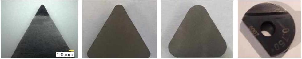
Figure 4. Tool types used in the machining study. Tools were carbide with cutting radii from 0.4 to 9.5. Image Credit: GGB
Figure 5a displays the machining configuration. The machining test part is held in a lathe while being single-point machined via the use of a toll held by a boring bar. The test part is then rotated, with the boring bar and cutting tool moved longitudinally along the part’s surface.
Two measures of machinability were employed in this study. General machining response was assessed via quantitative surface roughness measurements conducted using a Zeiss Surfcom 130A profilometer.
The surface condition was evaluated visually via imaging using a Keyence VHX-1000 microscope. This instrument offered high enough depth-of-field resolution to illustrate the condition of rough and curved surfaces.
Certain bearings’ dimensional response to the machining process was assessed separately. Parts used in the dimensional study were inserted into a fixed steel master die (Figure 5b) to ensure a consistent outer diameter and full roundness of the part.
Next, the master die and enclosed part were held in a lathe before the test part was machined via a method similar to the method displayed in Figure 5a.
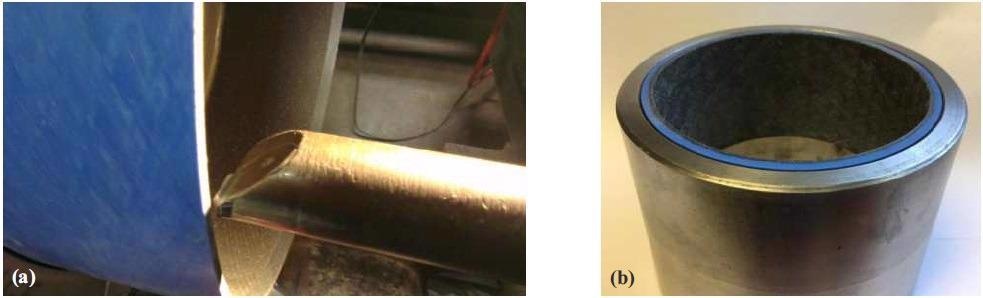
Figure 5. Image showing the methods used in the machining study. Image (a) shows a part being machined in the free state, used to analyze surface roughness following machining. Image (b) shows a machined part in a master die, used to evaluate dimensional response. Image Credit: GGB
Results
Two measurement methods were employed in quantifying machining response: surface roughness reported as average roughness (Ra) and internal diameter measured via coordinate measuring machine (CMM).
Roughness Measurements
Figure 6 and Figure 7 provide roughness data as functions of fiber type and machining parameters. Figure 6a and Figure 6b compare the discontinuous fibers to the continuous fibers as functions of cutting speed and tool radius.
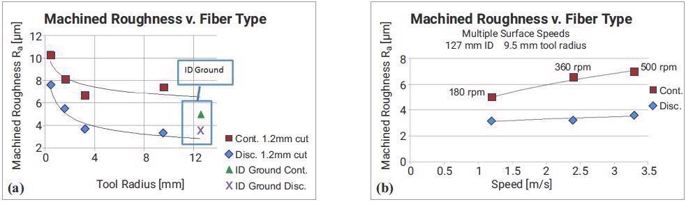
Figure 6. Roughness data comparing machining response for continuous PTFE fiber structures and discontinuous. Data are shown as functions of tool radii and cutting speed. Image Credit: GGB
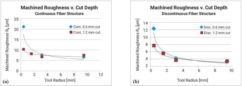
Figure 7. Machined roughness data showing impact of depth of cut. Graph (a) shows data for continuous PTFE fiber structure; graph (b) for discontinuous PTFE fibers. Image Credit: GGB
Tool radius ranged from 0.4 mm to 9.5 mm throughout the study, with roughness data confirming that the discontinuous construction provided significantly reduced roughness versus the continuous type. This was found to be the case through the entire range of tool radii.
Machined roughness was also measured and evaluated for ID ground samples. This was the incumbent method before the advent of the single-point tool machining method.
This roughness data highlights the improvement in roughness for the continuous fiber composite, but this remains rougher than its discontinuous fiber counterpart. The grinding method failed to demonstrate roughness improvement for the discontinuous fiber structure versus 3 mm or 9.5 mm radii tools.
It was determined that cutting speed had little or no impact on the discontinuous fiber composite’s roughness within the range tested. It was noted that continuous fiber structure was impacted by cutting speed, with increased speed causing increased roughness.
Roughness was measured as a function of cutting depth, with Figure 7 highlighting the impact of cut depth on roughness for the composites under investigation.
While neither composite type appeared affected by the cut depth at larger tool radii (producing finer finishes in both composite types), it was shown that the impact of tool radius was more pronounced at the smallest tool radius and lower cut depths for each fiber type.
Imaging of Machined Surfaces
Visual inspection of machined surfaces was undertaken to supplement the quantitative analysis of machining responses. Figure 8 displays surfaces of both composite types following ID grinding (the process specifically developed for machining the continuous fiber product).
The continuous fiber surface demonstrated minor fiber fraying, though this was regarded as standard and acceptable for the finished product. The discontinuous fiber surface (Figure 8b) revealed a smooth surface with no frayed or loose fibers, however.
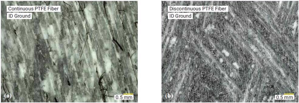
Figure 8. Surface image of the continuous PTFE fiber bearing using the baseline (ID grinding) process method for secondary machining (left, (a)). Image on the right (b) shows the discontinuous PTFE fiber bearing surface machined by the same ID grinding process. Image Credit: GGB
It is important to highlight that the roughness measurement of the discontinuous fiber composite surface was found to be smaller than the continuous fiber composite - 3.5 versus 5.1 µm Ra.
Figure 9 displays surfaces that had been machined with the smallest radius - 0.4 mm. These were found to exhibit the roughest measured surface of any tool radii within their respective data sets: 10.3 µm for continuous fibers and 7.6 µm Ra for discontinuous fibers.
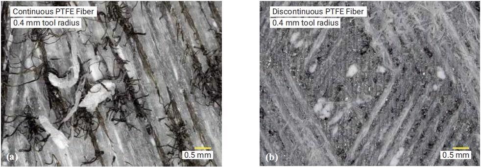
Figure 9. Surface conditions of the two materials following single point machining using a 0.4 mm radius tool. Image (a) shows the continuous PTFE fiber bearing and (b) the discreet PTFE fiber bearing material. Image Credit: GGB
The continuous PTFE fibers revealed a considerably frayed and fractured appearance. It was also noted that the surrounding fiber/resin matrix was altered in an unfavorable fashion, with machining chips of matrix material visible in the final machined surface.
The condition of the discontinuous fiber was visibly superior to that of the continuous fiber version, but it did demonstrate a degree of fiber fraying not seen with larger radii tools.
Figure 10 displays surfaces that had been machined with the largest (9.5 mm) radius tool. This shows that the continuous PTFE fibers exhibited a degree of fracture but less than experienced using the 0.4 mm tool.
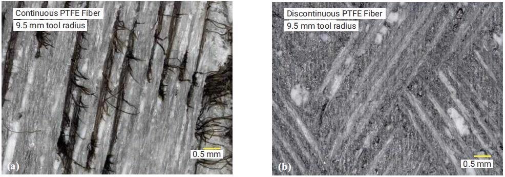
Figure 10. Surface conditions of the two materials following single point machining using a 9.5 mm radius tool. Image (a) shows the continuous PTFE fiber bearing and (b) the discreet PTFE fiber bearing material. Image Credit: GGB
It was also noted that the surrounding matrix did not reveal damage from the larger radius tool, unlike the 0.4 mm radius tool.
The surface of the discontinuous fiber composite that had been machined with the 9.5 mm radius tool exhibited no fiber fraying or other surface damage, again, unlike the 0.4 mm radius tool.
Figure 11 shows macroscale images of the surfaces of discontinuous PTFE fiber parts. The surface of these parts was found to be smooth, with no notable visual evidence of damage or other roughness.
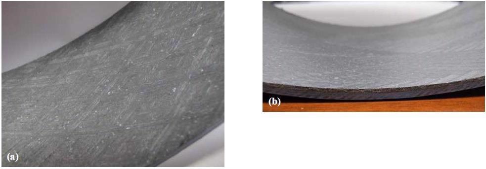
Figure 11. Macro images of the machined surface of the discontinuous PTFE fiber bearing liner, produced with a 3 mm radius tool. Images (a) and (b) were processed similarly, photographed at different angles. Image Credit: GGB
Dimensional Analysis
A master die (Figure 5b) was used to machine discontinuous fiber composites in order to evaluate dimensional response. Parts were removed from the die before being measured in their free state via CMM. This enabled the identification of their final diameter.
This diameter was measured at 3 points along the 75 mm bearing length, with measured diameters then compared to ISO tolerance ranges H4 to H7 (Figure 12).
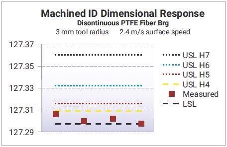
Figure 12. Dimensional results from discontinuous fiber bearing machined with a 3 mm radius tool. Dimensional ranges are shown for a range of tolerance limits as reference. Image Credit: GGB
Diameter data confirmed that the discontinuous fiber structure met the H4 tolerance range. It should be noted, however, that tolerance capability in ongoing production is linked to machining equipment’s ability to perform the appropriate process.
Conclusions
It was determined that cutting tool radius had a significant impact on the surface roughness of the final composite when using a single-point machining process.
The study also showed that discontinuous PTFE fibers bound in a thermoplastic fiber matrix were favorably responsive to single-point machining versus continuous PTFE fiber composites.
There was no evidence of cutting speed impacting machining response on the discontinuous PTFE fiber composite when speed was in the range from 1.2 to 3.3 m/s. However, cutting speed did impact the response of the continuous PTFE composites, with higher speed prompting increased surface roughness.
It was found that the dimensional capability of the discontinuous fiber bearing structure was within H4 tolerance, but this was dependent on the machining equipment used.
References
- Jacobsen, C., “Composite bearings having improved wear life,” US Patent 4867889, (1987)
- Jones,J., Palylyk, R., Willis, P., Weber, R., “Greaseless Bushings for Hydropower Applications: Program, Testing and Results,” CERL Technical Report 99/104, 1999
- Peng, Y., Kim, M., Horchuck,M., “Composite Bearings” EP1616107B1 (2007)
- Kim, M., Laicovsky, J., Rennie, K., Sarro, H., Trenkler,A. “Composite Bearing with Enhanced Wear and Machinability,” EP3189124 (A1) (2017)
- Kim, M., Wapner, E., Sarro, H., Ruscitto, L., “The reduction of tribo-oxidative wear in high frequency, low amplitude oscillation for wicket gate bearing applications,” Hydro 2015 (2015)
- Kim, M., “Effect of Shaft Corrosion Resistance on Fretting Wear with Composite Bearings,” World Tribology Conf., 2013
- Kim, M., “Tribo-oxidative Wear with Self-lubricating Bearings in High Frequency, Low Amplitude Oscillation,” STLE Conf., 2014
Acknowledgements
Produced from materials originally authored by Michael R. Kim and Elena Wapner from GGB.

This information has been sourced, reviewed and adapted from materials provided by GGB.
For more information on this source, please visit GGB.