Introduction It has been widely accepted that non-metallic inclusions in steel have considerable effects on the wear of cutting tools. Trent et al. [1] stated that deposited layers containing Al, Si and Ca on the rake face of carbide cutting tools used to machine steels are a main reason for an increase in tool life and cutting speeds. However, the existence of Al2O3 in steel has detrimental effects on tool life. Kiesling [2] explained the role of the size of MnS inclusions in steel on the life of cutting tools with respect to changes in deformation zones. According to him, large MnS inclusions have more tendency to reduce shearing deformation in the shear plane compared with small ones. In addition, large inclusions reduce friction between work and tool materials but small inclusions increase it. Therefore, better tool life can be achieved when the workpiece becomes smaller due to cutting because MnS inclusions near the center are larger than near the outside. Shaw [3] pointed out the role of non-metallic layers in reducing friction between the chip and rake face in term of the hydrodynamic action due to the formation of a wedge shaped liquid or semi-liquid layer between chip and tool. Thin layer results from thermal softening and spreading of non-metallic elements in the work material. Opitz [4] pointed out the pattern of these layers and proposed conditions for their formation. He proposed that the temperature in the secondary deformation zone must be high enough to cause non-metallic inclusions to deform plastically. The deformed inclusions need to have high enough affinity with the tool material to adhere firmly on the rake face at a distance from the cutting edge so that they are not swept away by the sliding chip on the rake face. Palmai [5] used TiN-coated M2 turning tools to machine conventional and free-machining 45 steels. The deposited layers originating from non-metallic inclusions in the work material on the rake face were evidently the major cause of long tool life. Similarly, Kankaanpaa et al. [6] found that tool life increased by 40 - 500% when TiN-coated tools were used to machine medium carbon steels deoxidized during the steel making process by Ca. This benefit results from the formation of non-metallic layers containing Mn, Ca and Si on the rake face of the cutting tool. The existence of the deposited layer on the rake face of TiN-PVD coated cutting tools used to machine medium carbon steel was clearly dependent upon the shape and size of silicate inclusions. However, the chemical composition of the layer is affected not only by the pattern of temperature developed but also by the area of the heat affected zone (HAZ) in the tools that influences directly the rate of tool wear [7-9]. Conditions for the formation of the deposited layers on the rake face of PVD-TiN coated HSS cutting tools and their influence on tool wear are detailed in this study. Experimental Tools used in this study were CVD-TiN coated HSS turning inserts as-received condition. They were HSS inserts, types PM-41 and T15. Their chemical compositions were obtained by spectrographic analysis shown in Table 1. Their shape is schematically drawn in Figure 1. The rake face of the inserts was firstly ground off to clear chip breaker grooves. Then, they were PVD-TiN coated using a low voltage electron beam system. Composite micro-hardness of the rake face at a load of 100 g was 1024 ± 25 Vickers hardness (HV). The thickness of the TiN coating layer was 2.5 ± 0.2 μm. Geometric parameters of the inserts were measured as follows: rake angle (γ = 0°); flank angle (α = 7°); inclination angle (ϕ1= ϕ2= 50°). Cutting conditions in the study were selected as follows: cutting speed 51 m/min; feed rate 0.22 mm/rev; depth of cut 1.25 mm. | 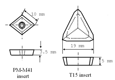
| | Figure 1. Schematic diagram of the two types of HSS inserts used in the study. | Table 1. Chemical compositions of the two types of HSS inserts used in the study. | | | PM-M41 | 1.02 | .34 | .25 | .015 | .024 | .50 | 4.35 | 4.61 | .10 | 1.86 | <.05 | 5.3 | 6.62 | | T15 | 1.5 | .45 | .40 | .019 | .018 | .22 | 4.57 | .45 | .01 | 4.25 | | 5.28 | 12.0 | The three hot rolled steel bars used as workpieces for turning experiments were of approximate dimensions 120 mm diameter and 900 mm length. The first two bars (denoted as W1 and W2, respectively) were K1050 steel with a Vickers hardness of 210 ± 25 HV at a load of 300 N and the third bar (denoted as W3) was 1045 steel with Vickers hardness of 200 ± 20 HV at the same load. Their chemical compositions were obtained by spectrographic analysis as shown in Table 2. Table 2. Chemical compositions of the workpieces used in the study. | | | W1 | .50 | .74 | .06 | .006 | .022 | .02 | .02 | .02 | .01 | <0.01 | <0.01 | <0.01 | .005 | | W2 | .50 | .79 | .06 | .006 | .025 | .02 | .03 | .02 | .02 | <0.01 | <0.01 | <0.01 | .005 | | W3 | 0.455 | .696 | .364 | .026 | .015 | .154 | .172 | .023 | .147 | | | | .022 |
Workpiece samples were obtained from the bars by cutting along two planes, perpendicular and parallel to their axis. They were then ground and polished using diamond paste with grit size of 1 μm. After that they were examined by scanning electron microscopy (SEM) to determine the size, shape and chemical compositions of inclusions. After cutting, the inserts were examined by SEM. To determine the temperature pattern developed in the tools using the Trent and Wright method [1] and tool wear, cross sections were made to obtain tool samples by cutting in the plane perpendicular to the cutting edge at the middle of its real cutting length. The samples then were ground, polished and etched in 4% Nital solution for 30 seconds. Results and Discussion Chemical compositions obtained by spectrographic analysis of the workpieces W1, W2 and W3 were shown in Table 1. It is clear that workpieces W1 and W2 were nearly identical in chemical composition. Metallographic examination of the three workpieces revealed a microstructure of ferrite with colonies of pearlite and the presence of inclusions. Silicate inclusions and sulfide inclusions were revealed in the three workpieces. Figure 2(a) is on SEM of a silicate inclusion in a longitudial section from workpiece W1. In cross section, it had diametral dimensions of approximately 2.5 μm to 3.5 μm. Its chemical composition obtained by Energy Dispersive X-Ray (EDX) analysis indicated mainly Mn, Si, Al and little Fe, Ca, S, Ti, as shown in Figure 2(b). In workpiece W2, similar silicate inclusions were also found but their diametral dimensions were approximately 1.5 μm to 2.5 μm. A second type of silicate inclusions was found in both workpieces W1 and W2, where EDX analysis revealed mainly Fe, Mn and a little Si, Ti. | 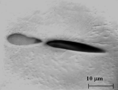
(a) 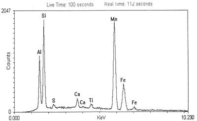
(b) 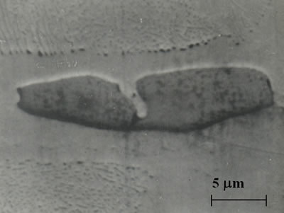
(c) 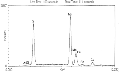
| | Figure 2. (a) Scanning micrograph of a silicate inclusion found in workpiece W1. (b) EDX analysis of the silicate inclusion showing its chemical composition. (c) Scanning micrograph of sulfide inclusion found in workpieces W1 and W2. (d) EDX analysis of the sulfide inclusion showing its chemical composition. | In 2(c), an SEM of the first type of sulfide inclusion in a longitudial section found in both workpiece W1 and W2. Its chemical composition obtained by EDX analysis detected mainly Mn, S and little Fe, Cu, as shown in Figure 2(d). Complex inclusions were found in both workpieces W1 and W2. These inclusions were in two parts, as shown in Figure 3(a). EDX analysis of the globular part showed its chemical composition (Figure 3(b)) to be quite similar to the sulfide inclusions analyzed in Figure 2(d), except that the percentage of Fe is higher. | 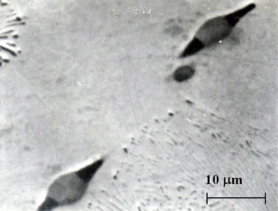
(a) 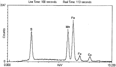
(b) 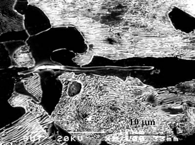
(c) 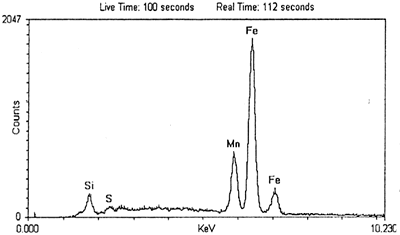
(d) | | Figure 3. (a) Scanning micrograph of a complex inclusion found in workpiece W1 and W2. (b) EDX analysis of the globular part in (a) showing its chemical composition. (d) EDX analysis of the tail part in (a) showing its chemical composition. (c) Scanning micrograph of sulfide inclusions detected in workpiece W3. | EDX analysis of the deposited layers on the rake face of the PVD-TiN PM-M41 insert in Figure 4(a) showed a chemical composition similar to that of the silicate inclusions analyzed in Figure 2(b). Moreover, EDX analysis of the deposited layers on the rake face of the PVD-TiN T15 insert in Figure 4(b) found a mixture of silicate and sulfide inclusions analyzed in Figure 2(b) and 2(d). The difference in chemical composition of the deposited layers may result from difference in temperature distribution on the rake face of the two types of inserts due to the dissimilarity of heat transfer rate from the cutting area, as described in study [8]. Sulfide inclusions are softened at lower temperatures compared with silicate inclusions. | 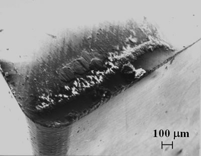
(a) 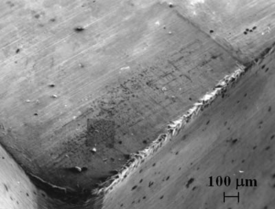
(b) 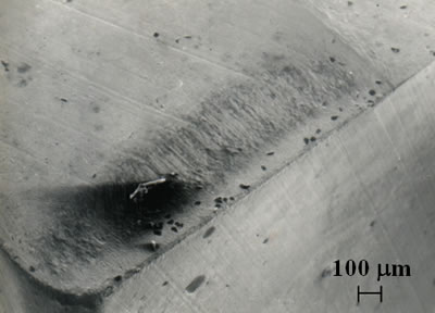
(c) 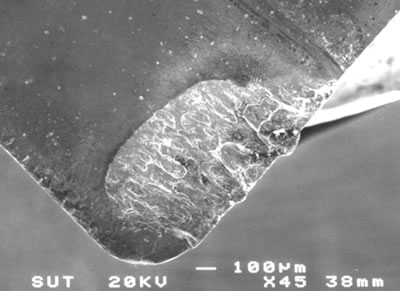
(d) | | Figure 4. (a) Scanning micrograph of the rake face of a TiN coated PM-M41 insert used to machine workpiece W1 after 2 min showing deposited silicate layers. (b) Scanning micrograph of the rake face of a TiN coated T15 insert used to machine workpiece W1 after 0.5 min showing a mixture of deposited silicate and sulfide layers. (c) Scanning micrograph of the rake face of a TiN coated PM-M41 insert used to machine workpiece W2 after 2 min showing low silicate inclusion transfer. (d) Scanning micrograph of the rake face of a TiN coated PM-M41 insert used to machine workpiece W3 after 2 min showing no deposited layers. | It is very interesting to note that neither the silicate nor the sulfide inclusions with high Fe peaks were unable to deposit on the rake face of either PVD-TiN coated PM-M41 (as shown in Figure 4(c) and 4(d)) or of PVD-TiN coated T15. This can be explained by a higher plastic deformation temperature of Fe compared with the silicate and sulfide inclusions. So the high Fe inclusions could not deform plastically at the cutting temperature of approximately 650°C at the chip/ tool interface, but at that temperature both silicate and sulfide inclusions are able to deform plastically [8]. Moreover, Fe has less affinity with TiN, as described in [5-7]. It can be seen from Table 2 that in workpiece W3 the contents of Si, Mn and Al that are the main elements of silicate inclusions were about 4-6 times higher than in workpieces W1 and W2. These elements did not form silicate inclusions like those in Figure 2(a) but may be separate oxides, resulting in an increase in wear rates due to abrasion as shown in Figure 4(d). EDX of analysis there as the region rear the crater wear of Figure 4(d) found high contents of Al. That may be evidence of Al2O3 which is detrimental to the TiN coating layer and a source of abrasive grits. This result is consistent with Trent et al. [1]. The application of PVD-TiN coated tools to machining medium carbon steel at high cutting speeds results in the elimination of a built-up edge (BUE), particularly when deposited layers are formed on the rake face of the coated tools [7]. The formation of the deposited layer may change the frictional contact condition between chip and rake face, and as a result a white layer (shown by SEM) forms on the crater wear as shown in Figure 5(a), even in the case when small silicate inclusions are deposited on the rake face. The white layer has two sub-layers, a top-heavy deformed sub-layer and the sub-layer below it, as sketched in Figure 5(b). EDX analysis of the top-heavy deformed layer showed a chemical composition of the work material as in Figure 5(c). This sub-layer may play a role in preventing adhesion between chip and tool material in the crater wear, resulting in low wear rates. EDX analysis of the sub-layer showed a chemical composition of tool material as in Figure 5(d). This sub-layer may be gradually weakened due to diffusion of tool material into work material at the chip/tool interface and then wearing away. The subsequent white layer then forms on the crater wear to protect the tool material from high wear rates. | 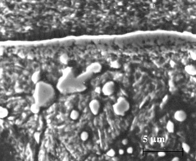
(a) 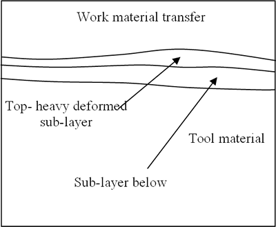
(b) 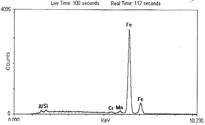
(c) 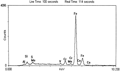
(d) | | Figure 5. (a) Scanning micrograph of a cross section of a PVD-TiN coated insert showing a layer in the crater wear. (b) Sketch of the white layer in the crater wear of the TiN coated tool. (c) EDX analysis of the heavily deformed top layer in (a) showing its chemical composition of work material. (d) EDX analysis of the sub-layer in (a) showing its chemical composition of tool material. | Conclusions Under the cutting conditions used in this study, the formation of the deposited layers originating from inclusions in the steel workpiece depends on the existence of silicate inclusions and their dimension in cross section. Large silicate inclusions are preferable for layer formation. The chemical composition of the layers is the same as that silicate inclusions or a mixture of silicate and sulfide inclusions. The chemical composition of the deposited layers depends on temperature developed in the rake face region of the coated cutting tools. However, all the high Fe inclusions found in the steels would seem impossible to be deformed plastically and adhere firmly on TiN coatings to form deposited layers. The deposited layers can eliminate built-up edge (BUE) and reduce crater wear by the protective action of the white layer formed in the crater. Acknowledgements Dr. Q.T. Phan would like to acknowledge the support of the Swinburne University of Technology- Australia and Suranaree University of Technology-Thailand during the period the work was implemented. References 1. E. M. Trent and P. K. Wright., Metal Cutting, Fourth Edition, Butterworth-Heinemann, USA, (2000). 2. R. Kiesling and N. Large., Non-Metallic Inclusions in Steels, the Metals Society, London, (1975). 3. M. C. Shaw, Metal Cutting Principles, Oxford University Press, New York, (1991). 4. H. Opitz., “Tool Wear and Tool Life”, International Research in Production Engineering”, the American Society of Mechanical Engineers, New York, (1963) 107-113. 5. Z. Palmai, “Formation of non-metallic protective layers on high speed steel tools”, Metals Technology, 11 [1] (1984) 34-37. 6. H. Kankaanpaa, H. Pontinen and M. Korhonen, “Machinability of Culcium-Treated Steels Using TiN Coated High Speed Steel Tools”, Materials Science and Technology, 3 [2] (1987) 155-158. 7. Q.T. Phan, “An Examination of Tribological Contact between Chip and Rake Face of PVD-TiN coated HSS Tools”, Master Thesis, Swinburne University of Technology- Australia, (1996). 8. Q.T. Phan; T.L. Banh, T.P.M. Nguyen and C.Q. Nguyen, “Deposited Layers on Rake Face of the PVD Coated Cutting Tools and their Effects on Temperature Distribution in the Tool”, Journal of Science and Technology, Technical Universities, 16-8 (1998) 30-36. 9. Q.T. Phan, “A Study of Wear of PVD-HSS Coated Tools Using to Machine Medium Steels”, Journal of Industry, 6 (1999) 25-28. Contact Details |