|
Diamond-like carbon (DLC) coatings have excellent properties such as high wear resistance, very low friction coefficient, and high corrosion resistance. Because of these excellent properties, DLC coatings have attracted great attention for use in various applications in industries such as oil and gas, semiconductor, medical and automotive. In the oil and gas industry, DLC coatings are especially expected to improve tribological and corrosion performance of components that experience extreme environments provided the coating can be applied to internal surfaces of pipes, pipe joints, drilling fixtures, and drilling bores, etc. For piping or tubing that delivers corrosive material, obviously the interior surface that is in contact with the corrosive material is the surface that must be coated.
Deposition Methods for Diamond-Like Carbon Coatings
There are several methods available to deposit DLC or other coatings at the outer surface of components; such as chemical vapor deposition (CVD), physical vapor deposition (PVD), electroplating, flame spray, and sol-gel. However, coating internal surfaces remains a challenge especially for large aspect ratio (length to diameter ratio) components and very limited information is available in the literature.
In the case of very low-pressure techniques such as PVD, where the pressure is below or near the molecular flow region, coating internal surfaces have been limited to tubing with large diameters and short lengths, due to line of sight deposition. CVD techniques are limited in this application as well, due to the need to supply heat for the chemical reaction, which damages heat-sensitive substrates. PECVD (plasma-enhanced chemical vapor deposition) can be used to lower the temperature required for the reaction, but then there is difficulty in maintaining a uniform plasma inside the pipe and preventing depletion of the source gas as it flows through a pipe placed inside a vacuum chamber.
Plasma Enhanced Chemical Vapor Deposition of Diamond-Like Carbon Coatings
This article reports the result of a study demonstrating the potential of a new PECVD technology to deposit DLC based films on internal surfaces of pipes with excellent corrosion and wear resistance characteristics. The results are obtained on rough ( Ra ~ 110µin) carbon steel substrates through the use of a multi-layer coating that provides strong adhesion to the substrate and reduced stress, as demonstrated for the former by the lack of corrosive undercutting between the substrate and the coating and for the later by the ability to deposit thick coatings.
Experimental
Coating Deposition
A novel hollow cathode plasma immersion ion processing method is developed and used to deposit silicon-containing diamond-like carbon (DLC-Si) films inside a one-foot long 1020CS pipe with 1.75-inch diameter (aspect ratio of 6.85). This method takes advantage of plasma ion immersion and high-density hollow cathode plasma generated within the pipe itself allowing decomposition of precursor and subsequent deposition of DLC-Si based films. As seen in Figure 1, this is done by negatively pulse biasing the pipe, which acts as the cathode, with anodes attached at the ends. A gaseous precursor is introduced and ionized causing a coating to be deposited on the pipe, with by-products pumped out.
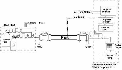
Figure 1. Diagram of Process Set-up
This technology is being used to deposit amorphous hydrogenated DLC-Si based coating on the internal surface of pipes with a variety of aspect ratios ranging as seen in Figure 2. Data reported in this article is for a 1-foot long pipe with 1.75-inch internal diameter. A detailed description of the technology is provided in an associated reference.
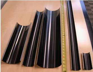
Figure 2. DLC-Si based coating deposited on the internal surface of pipes with a variety of aspect ratios.
Coating Structure
A layered coating structure was deposited onto the internal surface of a 1020CS pipe. The layers consist of three layers:
1. Germanium carbon adhesion layer, few seconds of Ge adhesion layer followed by high voltage Ar etch-back
2. Silicon doped DLC layers with silicon reducing and carbon increasing through the layers
3. DLC ‘cap’ layer.
Coating Thickness
A total coating thickness of 41µm was measured at the entry of the pipe using a standard calo-test method, see Figure 3 (as the 1020 CS surface is very rough, it is very difficult to see the individual layers). Approximately the layers consist of 0.5µm of an adhesion layer, 24.5µm of Six, C, and 16µm of DLC. The process conditions for each layer are summarized in Table 1. No external heating of the substrate was employed and the maximum temperature during the deposition (due to plasma heating) was 175°C.
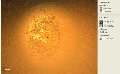
Figure 3. Optical micrograph of a Calotest crater showing structure.
Table 1. Table summarizing coating deposition process conditions
|
|
|
Adhesion
|
germanium precursor
|
70
|
240
|
0.5
|
0.3
|
|
SiC
|
Silicon and hydrocarbon precursor
|
120
|
180
|
24.5
|
|
DLC
|
hydrocarbon precursor
|
120
|
180
|
16
|
Coating Microstructure and Composition
For microstructure and composition analysis, a combination of techniques was used including scanning electron microscope (SEM) transmission electron microscope (TEM), electron dispersive X-rays (EDX). Tribology property characterization includes wear rate, coefficient of friction, coating-substrate adhesion, hardness, and modulus measurement. The method to perform wear testing is in accordance with ASTM G133-02 using a tungsten carbide ball with a 5mm diameter. A normal load of 5N with a sliding distance of 200 meters and a stroke length of 10mm was used.
Coating Adhesion
The method of measuring adhesion is by ASTM C 1624 Single Point Scratch Test, where a 200µm diamond stylus is moved across the coating with progressively increasing load and the critical load (Lc3) is recorded upon film delamination from the substrate, the maximum load achievable with our tool is 30N.
Coating Hardness
Coating hardness and elastic modulus is tested using a micro-indenter as per reference 7. In this test, an indenter tip, normal to the sample surface, is driven into the sample by applying an increasing load up to a predefined value. The load is then decreased until partial or complete relaxation of the material occurs. The resultant load-depth curve is then used to calculate mechanical properties such as hardness and elastic modulus. Data reported in this article is based on a Vickers type indenter with an applied force to achieve a penetration of less than 10% of coating thickness. Values obtained from the test are hardness and modulus (in GPa).
Coating Corrosion Resistance
Corrosion resistance analysis was performed using exposure to 15% HCl at room temperature and 10% NaCl at 70C. Figure 6 shows the sample coupons of the coating exposed to 15% HCL and 10% NaCl for a duration of 24 hours. Visual and optical observations were performed for any failure mechanisms that may occur during this time and reported. Additionally, the samples were tested for corrosion resistance by exposure to a 30-day sour (1% H2S) autoclave test by an independent lab.
Results and Discussions
TEM Imaging of Coating Interfaces
The interfaces between DLC–Si coatings and steel substrate were investigated, as this interface is critical for preventing both delaminations of the film under high load conditions, such as abrasion and erosion, and also to prevent corrosive undercut of the film in the event the film is damaged or penetrated. Figure 4a shows a high magnification bright field cross-sectional TEM micrograph of the interfaces (region 2 in Fig. 4b) between the substrate and the coating. The XRD pattern shows some crystalline structure is present within the amorphous matrix at the interface while graded DLC-Si films are amorphous (region 9). Figure 4b shows bright-field TEM and associated EDX analysis which shows that the interface between the substrate and the layered adhesion layer contains mixing of substrate constituents with adhesion layer constituents. The copper is an artifact as the sample grid is made of copper. This layered adhesion structure with the mixing of substrate and adhesion layer constituents provides excellent adhesion preventing corrosive undercut in acid or NaCl exposure test even on rough (~110µin Ra) carbon steel substrates.
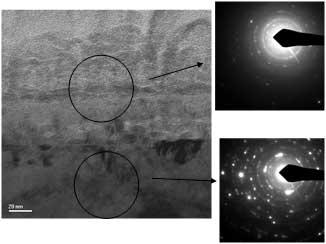
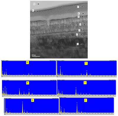
Figure 4. (a) High Mag. TEM micrographs and XRD patterns. (b) Bright-field TEM micrographs and associated EDX spectra showing substrate-coating interface.
SEM Imaging of the Coating Cross-Section
Figure 5 shows an SEM cross-section of a similar multilayer coating deposited by the same technique. In the SEM cameo image, the color is related to the atomic number, with brighter or warmer areas having higher average atomic number compositions. Thus the brightest area is the steel substrate followed by the regions deposited with a silicon precursor and the darkest regions being deposited with hydrocarbon precursor, while the intermediate brightness areas are deposited with blended silicon and hydrocarbon precursors. This SEM also shows the lack of any voids and the excellent coverage that is obtained over substrate defects by this coating technique.
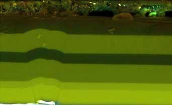
Figure 5. SEM cross-section of ~40-micron film on a steel substrate.
Coating Properties
Coating properties including hardness, modulus, adhesion by scratch test, and coefficient of friction and wear rate (in dry, and wet, abrasive bentonite mud environments) is shown in Table 2. It is clear that top DLC coating provides excellent hardness, COF as well as wear rate in comparison to an uncoated carbon steel substrate. Typically high sp3 content DLC films have higher compressive stress in addition to higher hardness, which can limit the thickness of these films. However, we are able to deposit coatings with high hardness with thicknesses up to 80µm indicating lower stress in the coating due to the addition of dopants as well as layered structure.
Table 2. Young’s modulus and Hardness of coating of 1020 carbon steel substrate. Modulus and hardness is an average of five measurements along the length of a 12-inch long pipe. Wear rate and coefficient of friction (COF) are also presented.
|
|
|
41
|
>30
|
100
|
171
|
14.6
|
2.7
|
0.05(dry)
0.04(bentonite)
|
|
|
|
DLC-Si
|
1.97E-06
|
1.56E-06
|
|
1020 CS
|
3.80E-05
|
3.40E-05
|
Corrosion Resistance of Diamond-Like Carbon Coatings
Corrosion resistance is measured by exposure for 24 hours to 10% NaCl solution at 150°F and 15% HCl at room temperature. Figure 6 (a and b) shows an optical micrograph of a coated 1020CS sample after exposure to HCl and brine solutions showing that DLC-Si coating provides excellent corrosion protection for the substrate. It is because DLC is chemically inert and acts as a physical barrier between the substrate and corrosion environment provided coating defects are minimized. It can also be noted that there is no corrosive undercut from the Rockwell C indent that was intentionally done to breach the coating, or from the exposed edges of the saw cut section, indicating the good adhesion and chemical inertness of the coating layer, at the interface with the substrate, as suggested by the TEM images.
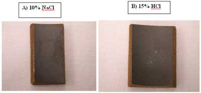
Figure 6. Optical micrograph of a coated 1020CS sample after exposure to a) 10% NaCl b) 15% HCl solutions for 24 hours.
Sour Autoclave Corrosion Test for Diamond-Like Carbon Coatings
Another corrosion test which the coating has been subjected to is a sour autoclave per NACE TM0185 standard. This is a three-phase test (aqueous phase – distilled water, organic phase – xylene, gas-phase – 1% H2S, 85% CO2, 14% methane) which is done at high pressure. Figure 7 shows the film (entry, middle & exit film of the pipe) before and after this aggressive test. It can be noted that the coating passed the NACE standard test with no damage or blistering of the coating occurring and additionally passed the standard 67V pinhole test before and after autoclave exposure. This test is well known within the oil and gas industry as a good measure of how corrosion resistant the coating is.
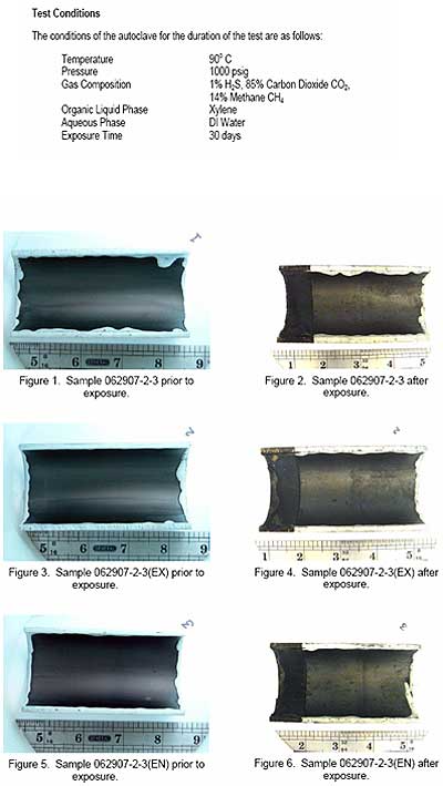
Figure 7. Coating before and after sour autoclave test and details of test conditions
Conclusions
A novel hollow cathode plasma immersion ion processing method is developed and used to deposit silicon-containing diamond-like carbon (DLC-Si) films inside a one-foot long 1020CS pipe with 1.75-inch diameter. A layered coating structure was developed, including an improved adhesion layer with good mixing of substrate and coating constituents, to improve adhesion of the coating while a DLC top layer provided excellent wear and friction characteristics. Data showed that such a coating provides excellent corrosion protection to internal surfaces of pipes. Application of this coating technology is in industries such as oil and gas, tribological and corrosion performance improvement is expected for components such as pump barrels, downhole pipes, drilling fixtures, and drilling bores, etc.
A complete set of references are available by referring to the source document.
|