In the extreme conditions that aircraft components face, the smallest imperfections can lead to dramatic reductions in performance. As the technology of aerospace develops, the demand for precision increases. Advancements in 3D metrology allow engineers to measure surface deformities down to the nanometer, ensuring optimal performance for their components.

Image Credit: MOLPIX/Shutterstock.com
Metrology Applications
Metrology refers to the study and practice of creating measurements as accurately as possible. 3D surface metrology, specifically, is the precise observation and measurement of a component’s 3D geometry to find extremely small-scale irregularities and deformations across its surface.
Typically, 3D metrology is performed using a Coordinate-Measuring Machine (‘CMM’). This machine uses an incredibly sensitive probe, capable of moving in all three axes, to touch the surface at set coordinates which can then be combined to create an estimation of the component's surface.
Although CMMs are commonly used, they have many disadvantages compared to their more contemporary counterparts. CMMs are bulky and expensive pieces of equipment meaning that, until recently, only very large manufacturers had the space and money to implement CMMs into their process.
Furthermore, CMMs can be slower to use, as the probe must be calibrated before it can be used. The contact of the probe itself can also be problematic when measuring sensitive components.
Advancements in Non-Contact 3D Metrology
For these reasons, newer non-contact technologies have seen a rise in recent years. The most commonly used non-contact 3D surface metrology systems are blue light scanners.
Rather than physically touching the component with a probe, blue light scanners will take several images of the component from various angles. With the use of scale bars and set calibration markers, these images can then be connected to form a single three-dimensional colormap of the component's surface.
Though this measurement method requires more labor than CMMs (most blue light scanners require the images to be taken manually), this system is much easier to implement as it relies more on software than large and expensive hardware.
Blue light scanning also means that much larger components can be measured accurately, as they are not confined to the dimensions of a CMM.
Companies such as GOM are aiming to reduce the increased manual input of blue light scanning. Their recent product, the ATOS 5, houses the component within scale bars which have calibration markers already placed on them.
The component is then rotated around as the camera periodically takes scans of the surface, giving a 3D colormap of the surface with minimal manual contact.
Although this technology is an improvement on CMMs in both speed, accuracy, and ease of use, the ATOS 5 shares their issues in its size. The initial advantage of non-contact scanning was that it does not require large and expensive equipment—an advantage that is lost by using a large ATOS 5 machine.
That being said, the machine’s ability to take measuring points of up to 12 meters in a single scan, while still being able to register surface deformations down to the nanometer, means its disadvantages are still heavily outweighed.
Metrology in Engineering
Metrology is essential to any industry where extreme precision is necessary, as small imperfections and uncertainties may lead to suboptimal performance. In the electronics industry, for example, metrology allows manufacturers to measure components down to the nanometer.
This is an essential part of electronic manufacturing, considering components in modern phones need to be incredibly small, with complex and precise geometries.
Metrology’s Applications in Aerospace
When considering industries where incredible precision is necessary, aerospace engineering is inevitably mentioned.
The extreme conditions that virtually every component of an aircraft is subjected to means that the smallest imperfection of a component can not only negatively affect performance but poses a potential safety risk to the entire system.
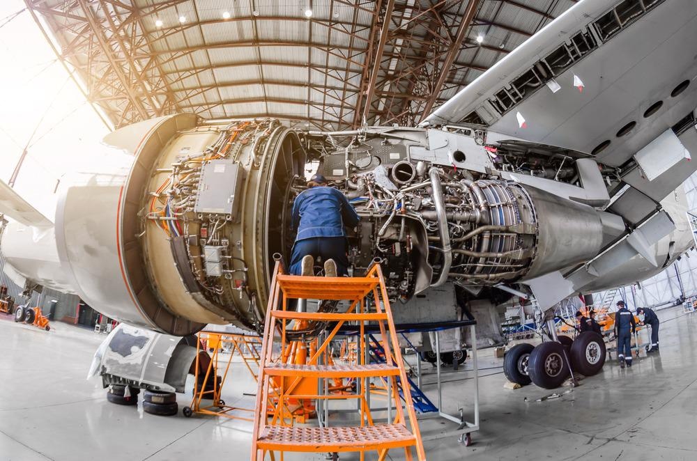
Image Credit: aapsky/Shutterstock.com
The main reason small deformations have such a large effect in the aerospace industry is due to mechanical modes of failure such as fatigue.
Enduring the stress of multiple cycles of pressurization and depressurization causes microscopic cracks to grow and propagate. Structural fatigue means that imperceptible cracks can lead to fatal accidents and total failure of an aircraft.
For this reason, there are many applications for optical surface metrology to be used in aerospace engineering.
The most simple and obvious of these applications is measuring the airfoil of the aircraft. An airfoil is the shape of an airplane wing, helicopter rotor, or turbine blade cross-section. Airfoils are typically defined by their maximum and minimum camber and thickness.
By using blue light scanning, or other optical metrology methods such as Nikon’s laser-based APDIS (a machine similar to CMMs, that uses lasers rather than a probe), engineers are able to accurately measure the thickness and camber of even the smallest airfoils accurately, and analyze how the thickness and camber may vary across the component’s body.
Furthermore, the surface of the airfoil can also be measured precisely, such that otherwise imperceivably small deformations across the leading blade edge will become visible with the use of a colormap.
In doing this, the manufacturers can pinpoint wear on the airfoil’s leading edge. These imperfections can negatively impact the performance of the component, so reducing them is beneficial to the behavior of the component.
Metrology can also be used to enhance the performance of an aircraft’s engine. Like the airfoil measurements, analysis of the engine’s fan and turbine blades can optimize its ability to generate thrust.
Additionally, the structure housing the engine can also be improved. Though slight changes in the engine’s shape may seem trivial, this geometry directly affects the airflow, which in turn affects the engine’s efficiency.
References and Further Reading
Celera Motion. (2021). 3D Metrology: Choosing the Best Frameless Motors. [online] Available at: https://www.celeramotion.com/news/articles/3d-metrology-choosing-frameless-motors
Exactmetrology.com. (2021). What is 3D Metrology? [online] Available at: https://www.exactmetrology.com/information/metrology-faq
GOM Metrology, (2016). GOM Webinar - Optical 3D Metrology for Aerospace Testing. [video] Available at: https://www.youtube.com/watch?v=78kRGW1a9HA&t=167s
Gom.com. (2021). 3D Measuring Solutions for Aircraft Structure. [online] Available at: https://www.gom.com/en/solutions/aerospace/aircraft
Gom.com. (n.d). ATOS 5 for Airfoil: Precise scanning of smallest details. [online] Available at: https://www.gom.com/en/products/high-precision-3d-metrology/atos-5/atos-5-for-airfoil
Kingsbury. (n.d). The what, how and why of 3D metrology. [online] Available at: https://kingsburyuk.com/the-what-how-and-why-of-3d-metrology/
Nikonmetrology.com. (n.d). Laser Radar Large Volume Metrology. [online] Available at: https://www.nikonmetrology.com/en-us/3d-metrology/large-volume-metrolog.
Precitec.com. (n.d). Optical metrology for consumer electronics. [online] Available at: https://www.precitec.com/optical-3d-metrology/industry-solutions/consumer-goods/
Disclaimer: The views expressed here are those of the author expressed in their private capacity and do not necessarily represent the views of AZoM.com Limited T/A AZoNetwork the owner and operator of this website. This disclaimer forms part of the Terms and conditions of use of this website.