Sponsored by GGBJan 14 2022
There is no right or wrong way to approach a mechanical design challenge, but some methods are smarter than others.
Ensuring the long-term, problem-free operation of a mechanical assembly requires consideration of every impact factor in the design process. It is only when every aspect of a mechanically-engineered aggregate operates well and fits together that it will maintain an optimal life cycle and good operating efficiency.
The majority of engineers will follow processes taught in university lectures. This traditional approach sees them collecting specifications and physical parameters, for example, accuracy and speed requirements or space limitations.
The engineer must understand the relevant acceptance criteria, acceptable project costs and design limitations before selecting a course of action.
Failure to meet performance specifications can doom a project, but it can also be hindered by cost overruns and over-designing. With parameters in place, engineers prepare their assembly and choose components that meet appropriate space and performance requirements.
Bearings are some of the most important components in a linear or rotary mechanical assembly. The engineer should consider a range of factors, including bearing type, speed, size and load.
Bearings are generally selected when the designer is required to incorporate one into their design. These are typically one of the last design components implemented.
A key aspect is frequently left without consideration, however - tribology. Tribological aspects should ideally be factored into a design from the outset. Doing so can enhance tribological contacts’ efficiency and working life, leading to a tangible improvement in high-level applications.
Tribology
Tribology is the science of friction, wear and lubrication. It also embodies the way that interacting surfaces and other tribo-elements act in relative motion in both artificial and natural systems (Figure 1).

Figure 1. Tribology in daily routines. Image Credit: GGB
Tribology is not an isolated discipline. It is a complex, interdisciplinary science where collaborative efforts lead to advances.
Tribological research involves professionals from fields as diverse as manufacturing, materials science and engineering, mechanical engineering, chemistry and chemical engineering, mathematics, physics, biomedical science and engineering, computer science and more.1,2
Tribological system analysis is key to investigating tribological impact factors.3
The goal of the system-technical method is to comprehensively describe a scientific field in its entirety. Entirety in this context means this field cannot be characterized by the intrinsic properties of individual system elements; instead, it must be characterized by the relationships between them.2
Tribological system analysis3 is used to describe and collate the full range of impact factors and how these affect the system’s functional and loss outputs (friction and wear). Tribological systems are comprised of the collective stress (operational inputs), the system structure and the functional and loss outputs.
System structure is defined by the substantial elements’ property profiles, including the base, opposing body and ambient medium.
The most frequently encountered contact configuration for a bearing contact is a hard-soft pairing which involves one surface being harder than the other. The softer of the two surfaces is typically the bearing surface because replacing a worn bearing is less costly than replacing a shaft.
Bearing materials employed in dry-running contacts tend to perform better when paired with a harder opposing surface.
Plain composite bearings are often chosen for their excellent sliding performance across large pressure-velocity (PV) ranges and their potential to be employed in lubricated or dry-running systems – a factor that makes them ideal for use a diverse array of applications.
Coatings represent a novel material family with good potential for lubricating surfaces operating in relative motion. Fiber-reinforced materials represent an ideal option for dry-running tribo-contacts, particularly when operating in demanding load conditions.
The second surface involved is the shaft, commonly known as the counter or opposing surface. The shaft material spectrum may feature polymers, hard and soft metals or coatings, with each of these materials requiring specific design consideration in relation to its own physical and chemical property profile.
The counterface’s topography also plays a central role, with each machining process resulting in a distinct topography pattern. The final element to consider is the environment, and while many applications have air as the surrounding medium, other gases are also possible.
This tribo-structure will be stressed with the operational input parameters. These parameters - known as collective stress - include the load, sliding speed and duration. They also include any movement and temperature conditions stressing the system structure.
The motion type is sliding for the majority of dry-running contacts. This follows a specific motion sequence that can be continuous, intermittent, oscillating or reversed. Its speed may reach high levels of approximately 4 m/s while the load spectrum ranges from very low to challenging loads over 100 MPa.
The loads are rarely static, with most applications requiring the contact to accommodate dynamic loads.
A combination of high loads and high speeds is rare, however, and tends to be short-lived when it does occur. This is important because ongoing operation at high load and high speed would cause overheating and destroy the tribological contact.
Figure 2 displays a range of impact factors that can affect performance. It also highlights that friction and wear characteristics should be considered system properties rather than intrinsic material properties.
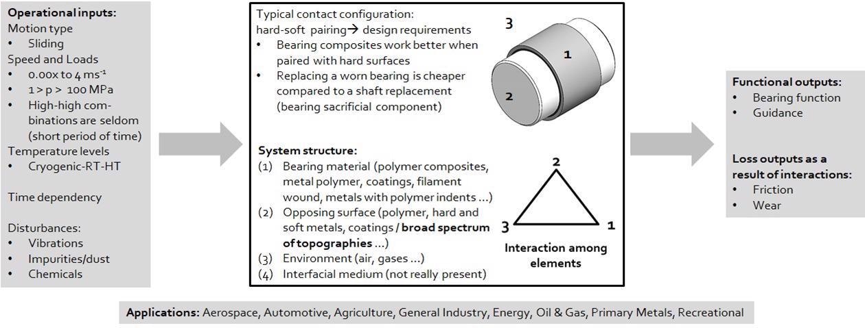
Figure 2. Dry-running bearing contact. Image Credit: GGB
Technical Surfaces
Faces employed in dry-running bearings are solid surfaces that contact the bearing and generate wear during relative motion. From an engineering standpoint, counterfaces are considered to be technical surfaces.
Technical surfaces characterize the geometrical limitation of technical components. A large number of technical surfaces employed in tribo-technical systems do not feature optimal and homogenous properties such as ideal smooth surfaces (Figure 3).
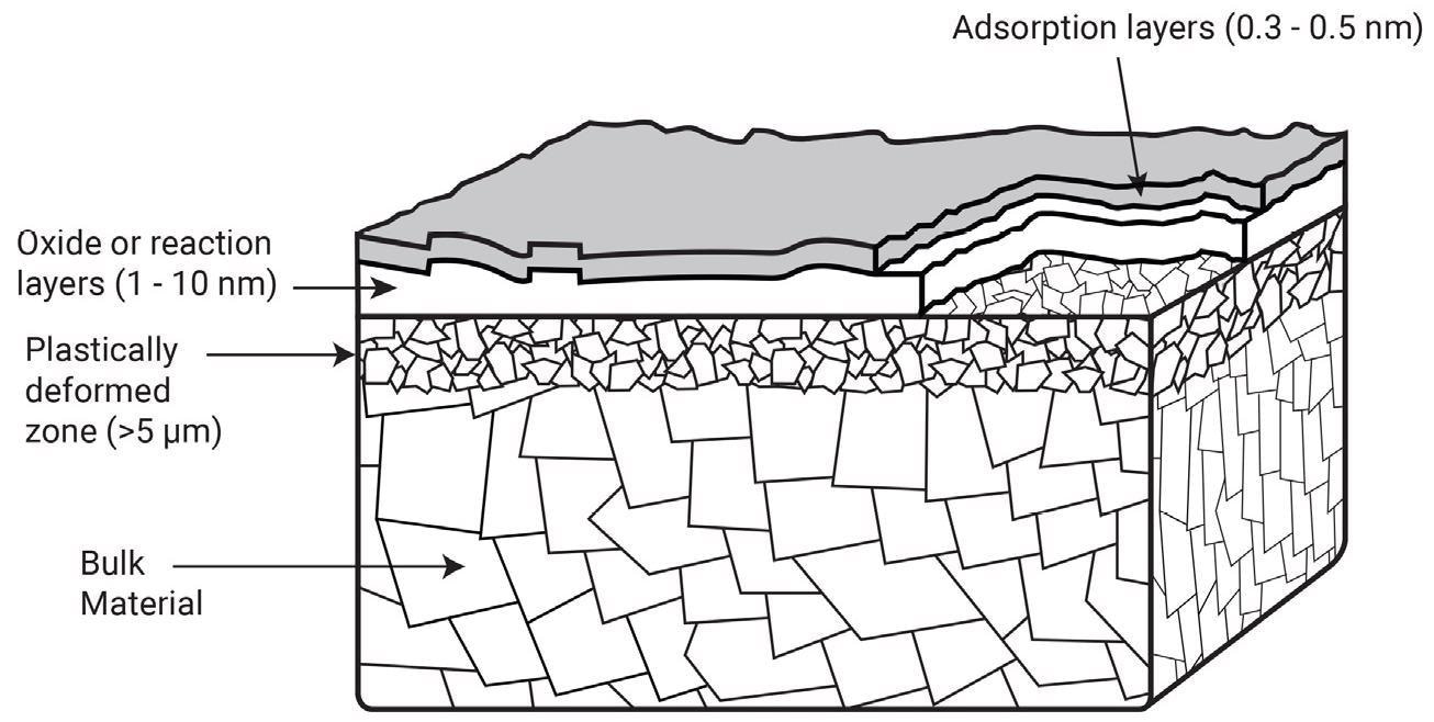
Figure 3. Multi-layer structure of a metallic surface. Image Credit: GGB
Metallic counterfaces are comprised of a multi-layer structure that incorporates the bulk material, the deformed material area via machining processes, adsorption layers, oxide and potential impurities.2
Surface treatments such as hardening or coating are standard methods to improve the top surface properties. These treatments lead to the formation of an additional layer, though each individual layer presents a distinct chemical and physical property profile.
Beyond the surface’s physical and chemical nature, microgeometry (topography) is a vital characteristic of technical surfaces. This is primarily determined by the processes employed during machining.2
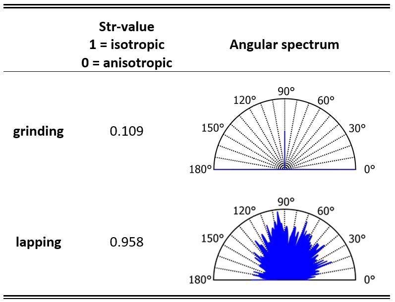
Figure 4 and Table 1 highlight commonly encountered surfaces generated via two popular surface finishing methods. They also demonstrate the resulting surface characteristics.
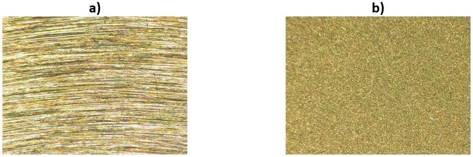
Figure 4. Surface characteristics. Image Credit: GGB
Table 1. Surface characteristics. Source: GGB
Wear and Friction
Friction is characterized as a tangential force resisting the relative motion of two bodies in contact. Wear is defined as damage to a solid surface, typically involving material loss, and triggered by relative motion between the surface and a contacting substance or surface.2
Protruding asperities result in technical surfaces that only contact one another in specific, limited areas. The sum of these micro-contacts is referred to as the real contact area. This is considerably smaller than the nominal contact area in terms of its geometrical dimensions.
Tribological interactions take place within the real contact area, and the tribology community has established four key friction and four fundamental wear mechanisms responsible for friction and wear generation.
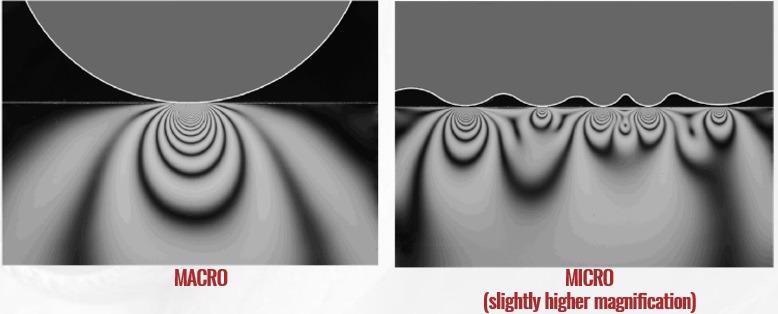
Figure 5. Contact of solids. Image Credit: GGB
The Impact of a Few Micrometers
The process of shaft surface finishing is a central factor in dry-running bearing contacts’ performance. The magnitude of the topography is just a few micrometers, but its effect on bearing performance is notable.
Metal-polymer composites and polymer composites are some of the most widely used plain bearing materials.
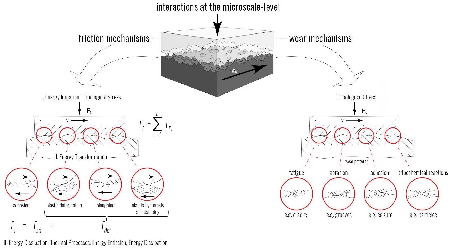
Figure 6. Friction and wear mechanism. Image Credit: GGB
Metal-polymer composites (Figure 7) are multi-layer structures comprised of:
- A PTFE bearing lining comprised of an impregnated anti-friction overlay enriched with PTFE and fillers
- A porous sintered bronze interlayer designed to ensure high wear resistance and act as a mechanical interlocking system for the PTFE bearing
- A liner
- A bronze or steel backing layer designed to ensure high mechanical strength
Polymer composites are comprised of a thermoplastic polymer matrix that has been modified with a PTFE filler. Figure 7 illustrates a microsection of material that features slide-active fillers distributed homogeneously in the matrix.
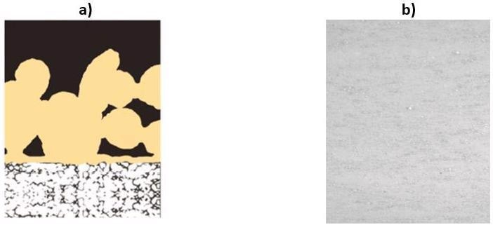
Figure 7. Structural design of the bearing materials. Image Credit: GGB
A key feature of dry-running bearing materials is their capacity to establish a transfer film on the counter surface. This protective film limits wear actions by filling any protruding roughness valleys and peaks.
Transfer films are thin structures, typically smaller than 1 µm, and formed by wear debris of the bearing material (Figure 8).
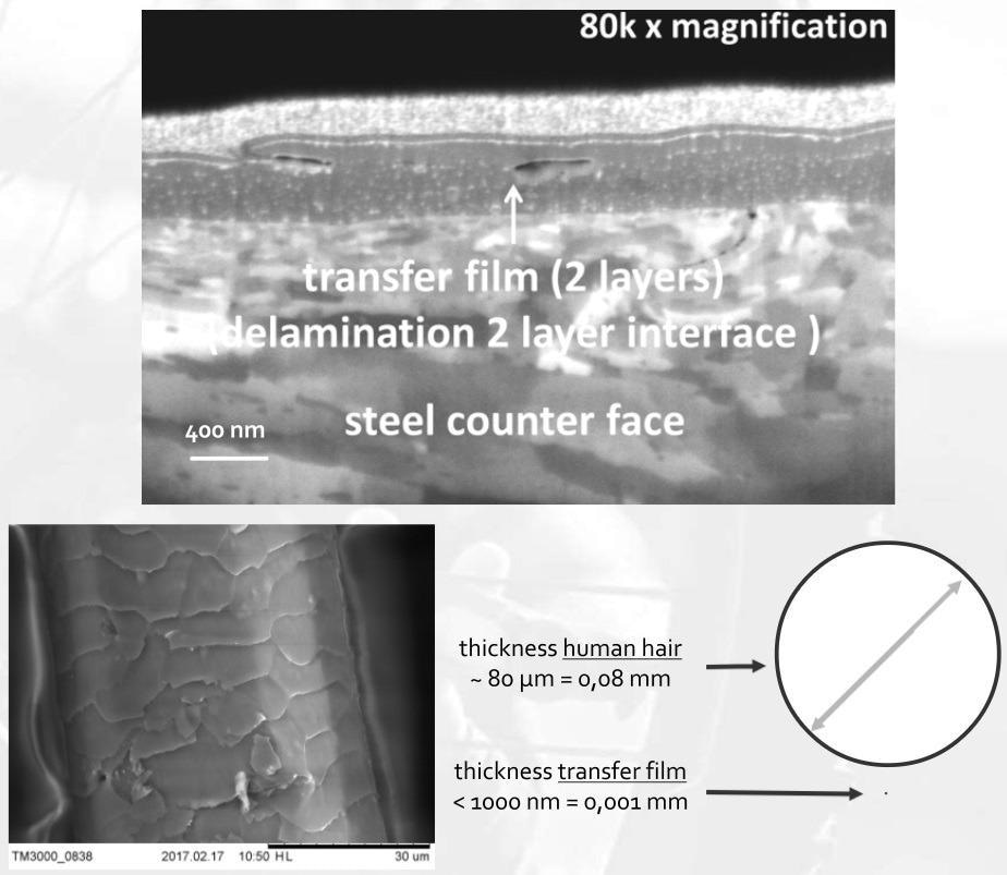
Figure 8. Structural design of the bearing materials. Image Credit: GGB
Polymer Composite Performance
In the example presented here, composite bearing materials were paired with a hardened 42CrMo4 counterface which featured two surface topographies employed in bearing applications: linear/flat and concentrically ground surfaces.
Figure 9 highlights the difference in wear performance of the polymer composite when paired with each counter surface. It also demonstrates the difference in wear performance when altering the roughness height level.
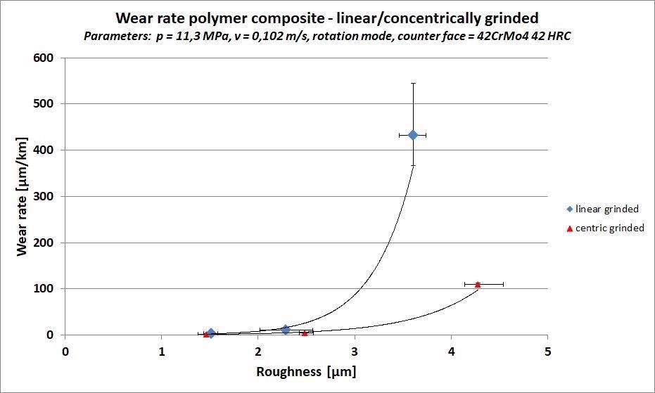
Figure 9. Impact counterface topography - polymer composite. Image Credit: GGB
Individual points in Figure 9 represent a mean value of at least three measurements, while the error bars signify the minimum and maximum measured value.
This study confirms that counterface topography is a leading factor in high polymer wear. Wear rates were measured over two orders of magnitude, with the optimal wear performance achieved when the composite was paired with the smooth concentrically ground surface.
The highest wear values (431 µm/km) were noted when evaluating a rough linear ground counterface. These results reveal a general trend of greater wear rates at higher roughness levels.
The wear in this example is caused by a higher level of abrasive induced wear. This is regarded as a critical wear mode for many polymeric materials and is a well-known effect in polymer tribology.2,4
This higher degree of abrasive wear at high roughness levels could be the result of a missing or insufficient transfer film evolution on rough counterfaces. In this instance, the transfer film did not accurately fill the asperity valleys and peaks.
A well-covering and well-developed film would better protect the polymer surface from damage by the opposing surface. It is possible to employ a scanning electron microscope (SEM) when looking to detect and visualize differences in transfer film quality.
The linear ground counterface demonstrated wear rates that were found to be two to four times higher than those of the concentrically ground shaft. Linear grinding results in the creation of valleys and peaks with a unidirectional orientation.
During continuous rotational sliding, however, the polymer pin is stressed twice perpendicular and twice parallel to the orientation of the topography. Higher wear is considered to be a result of stressing against the roughness peaks.
This significant shift in wear performance has a direct impact on the bearing contact’s working life, affecting the whole assembly.
Multi-layer Material Performance
Figure 10 displays the variation in wear performance of the multi-layer material. These findings reveal that the multi-layer material is less sensitive to topography changes than its polymer composite counterpart.
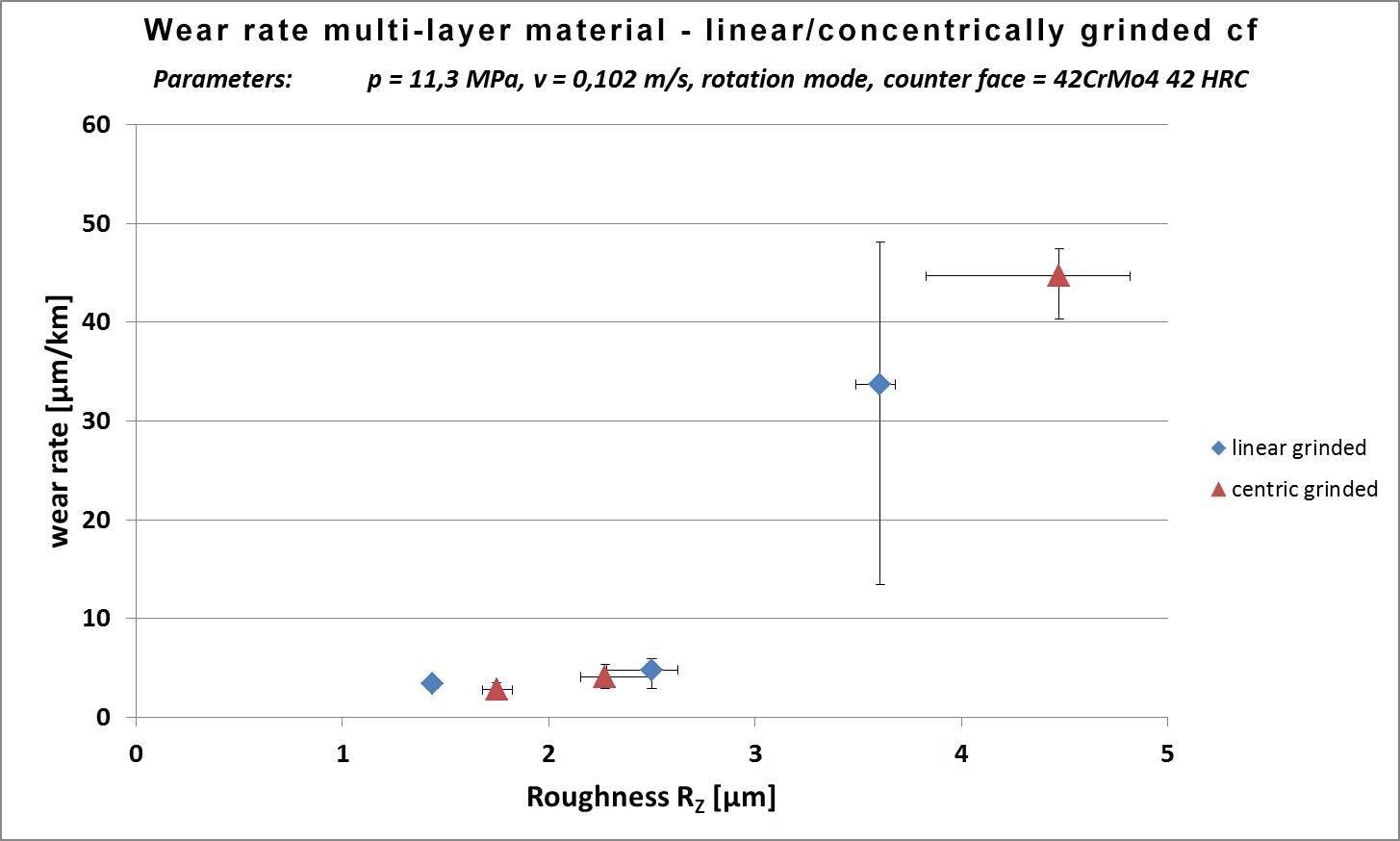
Figure 10. Wear performance of multi-layer material. Image Credit: GGB
Surface roughness height and topography orientation were both found to have a limited impact on wear performance due to the material’s multi-layer architecture. The material’s robust structure demonstrates a higher wear resistance and is able to smooth the initial steel roughness, resulting in the counterface being less aggressive.
Transfer Films and Wear Behavior
Abrasive induced wear is a critical wear mode for polymer composite materials. Missing or insufficiently formed transfer film causes increased wear because roughness peaks are not disguised and remain aggressive.
These findings were verified using energy-dispersive X-ray (EDX) spectroscopy analysis and SEM by analyzing systems with rough and smooth counterfaces (Figure 11a).
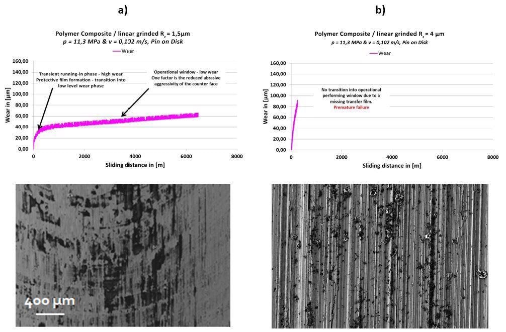
Figure 11. Polymer composite typical wear performances and SEM images of transfer films generated on smooth (a) and rough (b) linear ground counterfaces. Image Credit: GGB
Systems possessing smooth counterfaces tend to produce high wear rates within the initial few sliding meters. These then slowly decline as the system moves into the operational phase, typically after approximately 400 m.
The transfer film successfully masks the counterface, limiting its abrasive aggressiveness and improving wear performance.
Rough counterfaces tend to produce minimal wear debris and no transfer film on the steel surface. This effectively confirms that a missing transfer film is a central factor when experiencing high wear, also highlighting that rough counter surfaces may inhibit transfer film formation (Figure 11b).
These result in the creation of polymer debris that escapes the tribo-contact without depositing to the opposing surface.
SEM images reveal a well-developed transfer film on the steel counterface for multi-layer materials. This transfer film continuously covers the counterface, disguising initial grinding marks and leaving negligible areas of the initial metallic surface.
Covering the protruding roughness peaks in this way reduces abrasive wear actions, leading to low wear. This material’s performance can be attributed to a protective transfer film in synergy with the material’s robust architecture.
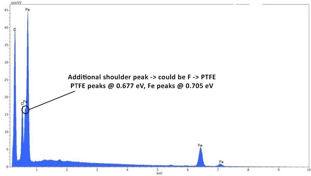
Figure 12. EDX-spectrum. Image Credit: GGB
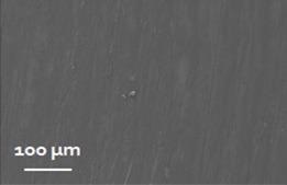
Figure 13. SEM image of the transfer film. Image Credit: GGB
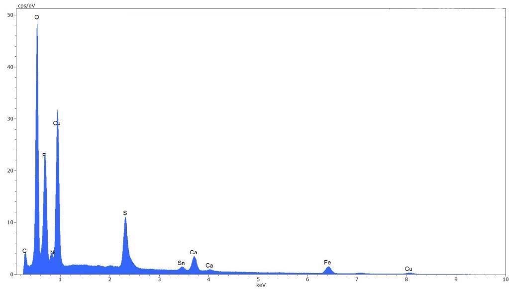
Figure 14. EDX-spectrum. Image Credit: GGB
Conclusion
When applying tribology, it is advisable to identify key application factors, including all tribological sub-systems. It is also prudent to identify solutions to improve the system and application.
These systems can be devastating for the application when not paid proper attention. Surface analysis and experimental tribological tests highlight that the topography of the attacking counterface has a major impact on the wear performance of bearing materials – both polymer and multi-layer materials.
References
- T. Mang, K. Bobzin, T. Bartels. Industrial Tribology: Tribosystems, Friction, Wear and Surface Engineering, Lubrication WILEY-VCH 2015, ISBN: 978-3-527-32057-8
- H. Czichos, K.-H. Habig. Tribologie-Handbuch: Tribometrie, Tribomaterialien, Tribotechnik Vieweg 2015, ISBN: 978-3-8348-1810-2
- L. Deters, A. Fischer, E. Santner, U. Stolz: GfT Arbeitsblatt Tribologie: Verschleiß, Reibung, Definitionen, Begriffe, Prüfung /
- H. Uetz, J. Wiedemeyer Tribologie der Polymere Hanser Fachbuch, ISBN: 978-3-4461-4050-9
- Kontaktmechanik und Reibung Ein Lehr- und Anwendungsbuch von der Nanotribologie bis zur numerischen Simulation Springer 2009, ISBN: 978-3-540-88837-6
Acknowledgments
Produced from materials originally authored by Marco Enger from GGB.

This information has been sourced, reviewed and adapted from materials provided by GGB.
For more information on this source, please visit GGB.