The adhesion of dielectric thin films has presented a major obstacle for interconnect integration and dependability. Issues such as film adhesion failures, reduced dielectric film mechanical integrity, and multi-layer interfacial cracking can all compromise device performance.
Underlying patterns and crystallographic structural mismatches drive debonding and delamination mechanisms, leading to dielectric layer failure. Understanding these processes in interconnect structures is essential for enhancing production processes and improving interconnect reliability.
Nanoindentation is typically used to measure thin film mechanical characteristics, including elastic modulus and hardness. For brittle films with weak bonding, indentation tests are also used to delaminate the film from the substrate, allowing interfacial fracture strength to be determined following this delamination.
In the study described below, a KLA InstrumentsTM iMicro nanoindenter equipped with a conical indenter tip was used to delaminate a low-k film on a silicon (Si) substrate to determine the critical delamination load. The interfacial energy released during delamination was calculated by directly analyzing loading-unloading curves.
Experimental Method
Indentation testing was performed using the iMicro nanoindenter equipped with an InForce 1000 actuator and a 10μm-radius conical tip to delaminate a ~340 nm low-k film on a Si wafer. Using a Berkovich indenter, the film hardness and elastic modulus were separately measured. The hardness was reported as 15.34 GPa, and the elastic modulus 2.341 GPa.
Sharp cube corners or Berkovich tips are often used to create fracturing in bulk hard materials. In brittle thin film coatings, however, these sharp pyramidal geometries cause rapid crack formation at very small loads, which results in chipping.
At the onset of loading, the sharp tip edges drive the formation of radial cracking, followed by delamination as the load increases. Conversely, spherical tips delay radial cracking at small loads, causing the failure mechanism to be dominated by delamination and interfacial cracking.
Indentation was performed according to the ISO 14577 test method using a constant loading rate. An array of 100 indents was produced with a maximum load of 200 mN, using a 0.98 decrement factor to calculate the critical delamination load. For 100 indents, the final indentation load was 27.1 mN. Optical micrographs were also captured using different objectives to measure the debonded area.
Note: The NanoVision stage on the G200X can also yield comparable crack length measurements by precisely imaging the entire indentation and cracking region. These findings will be published in a different article.
Indentation Testing Results: Delamination
Interfacial cracking and delamination occur during the indentation of low-k films. Delamination is generally the result of radial cracks reaching the coating-substrate interface and subsequently deflecting along it.
For sharp pyramidal tips, the delaminated region forms a sector of a disk surrounded by radial cracks (Figure 1a). Spherical tips act differently, generating multiple cracks within the indentation area. As the load increases, more cracks appear, growing through the coating toward the surface (Figure 1b).
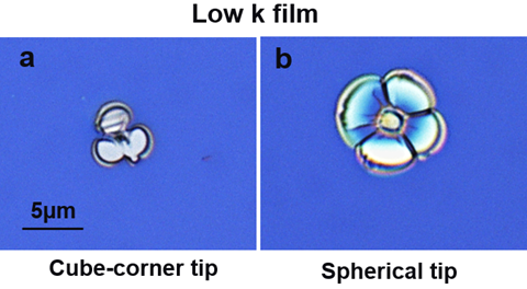
Figure 1. Nanoindentation delamination effects for (a) a sharp pyramidal tip, and (b) a spherical tip. Image Credit: KLA Corporation
Eventually, the delaminated film will buckle due to in-plane stresses caused by indentation. Pyramidal tip geometries produced non-uniform film cracking in the adhesion model used in this study, due to cracks radiating from the high stress concentrations at the indenter’s sharp edges.
By contrast, spherical tips initiated cracking in the sub-surface region and radiated in a symmetric pattern. For this reason, pyramidal tip delamination was not examined further.
The critical loads for crack and delamination initiation appear as discontinuities in the load-displacement curve (Figure 2). The first discontinuity, or pop-in event, was observed for the test ending at 47.4 mN
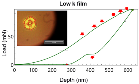
Figure 2. Critical loads that initiate cracking and/or delamination display discontinuities in the loading/unloading curve, as indicated by the red arrows. Image Credit: KLA Corporation
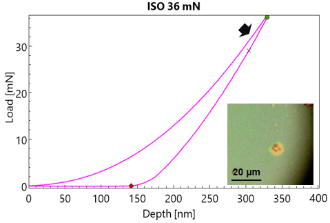
Figure 3. The load-displacement curve with a maximum load of 36mN does not show a discontinuity but does show initial cracking and delamination effects (inset). A slight change in slope, noted by the arrow, could be related to the initial cracking. Image Credit: KLA Corporation
Although displacement excursions and pop-in events are evident signs of failure, initial cracking and delamination in this sample occur at forces under 47 mN, as indicated in Figure 3.
Notably, the load-displacement curves reveal cracking through both acceleration in displacement and pop-in events at elevated forces during testing. KLA nanoindenters are sensitive enough to detect both types of interfacial cracking behavior.
Figure 4 presents the load-displacement curve for a test with a maximum load of 47 mN. As shown by the arrow, a clear discontinuity appears at approximately 43 mN. For repeated tests above this load, a pattern of pop-in events was observed within the 47 to 52 mN load range (top inset).
These findings suggest a load-dependent initiation threshold for pop-ins to occur, i.e., a single load (PCritical) where the first crack or delamination is anticipated. Pop-ins occur at indentation depths exceeding the 340 nm coating thickness, indicating significant elastic deformation of the film-substrate material beneath the spherical tip, elevating stress levels enough to drive film interface failures.
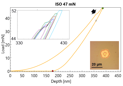
Figure 4. The load-displacement curve with a maximum load of 47 mN shows a pop-in event at ~42 mN. Repeated tests at higher loading (top inset) also show pop-in events at depths greater than the thickness of the low k film. Image Credit: KLA Corporation
As the indentation load increases, additional pop-in events appear in the load-displacement curve, indicating that the number of cracks in the delaminated area may correspond to these events.
Indentation Testing Results: Adhesion Energy
The energy required to extend a crack along the coating-substrate interface is termed interface adhesion energy or interfacial fracture energy. Indentation enables calculation of the work beneath the load-displacement curve, or dissipated energy, to extract the interfacial fracture toughness.
In practice, it remains challenging to distinguish between cohesive failure in the coating or substrate and true interfacial cracking (delamination).
When the full fracture or first clear pop-in event appears in the load-displacement curve, a near-constant delaminated area surrounds the indent. After this first fracture or pop-in event, additional loading increases radial cracking within the delaminated region. Extreme loading conditions may cause chipping and material ejection, resulting in large damage radii and multi-mode fracture events, conditions best avoided in adhesion studies.
The general definition of work as the total energy, or work done during indentation, is as follows:
 |
(1) |
This work is defined as a function of elastic strain energy, plastic energy or yielding, interfacial cracking or delamination, with a portion of heat (Q) dissipated. Of these energy components in Equation 1, only the elastic energy is reversible.
As demonstrated in Figure 5, the plastic work from indentation is calculated by subtracting the elastic work under the unloading curve (Figure 5a) from the total work of indentation represented by the loading curve (Figure 5b). Assuming that heat dissipation during indentation is negligible, the irreversible work corresponds to the plastic work plus the work done for cracking and delamination.
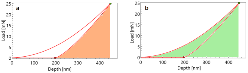
Figure 5. The elastic work (a, shaded) is recovered during unloading. The total work (b, shaded) includes both plastic and elastic work and is the area under the load-displacement curve. Image Credit: KLA Corporation
To calculate the adhesion energy of delamination, two consecutive tests are considered: a test showing a cracking (pop-in) event surrounded by full delamination, and a prior test that exhibits an elastic-plastic response without cracking. The adhesion energy calculation is illustrated in Equation 2.
The work divided by the delamination area represents the interfacial delamination energy, detailed in Equation 3, where A is the delamination area calculated from optical micrographs.
| ΔEcrack = ECritical – ECritical–1 |
(2) |
 |
(3) |
Table 1 illustrates the calculated interface adhesion energy values for multiple low-k coating samples, determined using the technique described above.
- Tfilm represents film thickness
- Pcritical is the test load at which the first pop-in event was clearly identified
- D is the radius of the conical tip used for indentation, which is constant for all samples
- ΔEcrack (J) is the work or energy determined for each sample (numerator of Equation 3)
- Rcrack is the radius of the crack or delaminated area
- γ is the interfacial delamination energy.
Table 1. Interface Adhesion Energy. Source: KLA Corporation
| |
Sample 1 |
Sample 2 |
Sample 3 |
Sample 4 |
| Tfilm (nm) |
353 |
359 |
369 |
371 |
| Pcritical (mN) |
47.4 |
50.3 |
44.6 |
50.3 |
| Dindenter (μm) |
10 |
10 |
10 |
10 |
| ΔEcrack (J) |
1.33E-9 |
1.48E-9 |
1.10E-9 |
1.55E-9 |
| Acrack (μm2) |
235.96 |
233.98 |
235.96 |
268.80 |
| γ (J/m2) |
5.66 |
6.33 |
4.68 |
5.77 |
These findings show the method described is capable of capturing subtle variations in interface adhesion energy. The minor differences in calculated results could be due to a real variation in bonding strength for different thin films during the thin-film deposition process.
Summary
KLA nanoindenters can measure slight variations in the interface adhesion energy of thin film samples. In this study, a KLA iMicro nanoindenter was used to measure the interface adhesion energy of low-k materials.
Using the ISO 14577 standard method with a decremental loading factor enabled the determination of the load required to initiate cracking or delamination at the film-substrate interface. Energy dissipation during indentation was evaluated for load-displacement curves near the critical load.
The demonstrated methodology can also be applied to other brittle film-substrate material systems where plastic deformation of the film/substrate during indentation is minimal and most of the applied energy drives elastic work and interfacial debonding.

This information has been sourced, reviewed, and adapted from materials provided by KLA Corporation.
For more information on this source, please visit the KLA Instruments website.