Introduction Optical disks and diffraction gratings are widely used optical devices. Analysis of optical devices is currently dominated by scalar diffraction theory and the geometrical optics technique because the refraction type of optical device is designed based on refraction theory. Recently, continuing advances in fine-structure building processes and computational capacity have resulted in the development of various structures and devices that are slim and lightweight and possess other new features. However, the finite-difference time domain (FDTD) method [1, 2] is considered because a weakness of diffraction theory is the analysis for structure of wavelength size. The FDTD method represents a powerful approach to a direct solution of Maxwell's equations, both in space and time. In this study, we analyzed light-wave propagation of a laser-induced liquid crystal (LC) lens [3, 4] using to two-dimensional FDTD method. The laser-induced LC lens was formed photothermally [5-8] in dye-doped LCs (DDLCs). The laser-induced LC lens was varied over a wide range by using both large optical non-linearity and anisotropic complex refractive indices in GHLCs. The characteristics were strongly dependent on the polarization state of the probe beam because the sign of the temperature coefficient was negative for an extraordinary wave while positive for an ordinary one. The temperature distribution in the LC layer was calculated by three-dimensional heat-conduction analyses [7, 8]. The refractive index was determined from temperature by the temperature dependence of the refractive indices. Light-wave propagation over the refractive index distribution was analyzed by means of the FDTD method. Furthermore, the far-field electric intensity pattern was calculated using diffraction theory [9, 10]. The Laser-Induced LC Lens The nematic liquid-crystal (NLC) (4'- pentyl - 4 - biphenylcarbonitrite, 5CB) was obtained from Merck Japan Ltd. Figure 1 shows the measured temperature variation of the refractive index of 5CB. The nematic - isotropic transition temperature of the 5CB is 36°C according to the physical characteristic data provided by the manufacture. Commercially available Disperse Red 9 (DR9) was obtained from the Aldrich Company Ltd., and was used as the doped dye without further purification. The DDLC was sandwiched between two parallel transparent glass substrates. The inner surfaces of the two substrates were coated with thin poly-vinyl alcohol films and unidirectionally rubbed, and the space between them was maintained by polyester spacers. In this case, the DDLC was regarded as a uniaxial single crystal, and we define the extraordinary ne and ordinary no refractive indices according to the strong and weak absorption coefficients, respectively. The dye concentration was set to be 0.8 wt% for 20 μm-thick samples. | 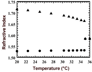
| | Figure 1. Temperature dependence of the extraordinary (▲) and the ordinary (●) refractive indices of 5CB. | Experimental Figure 2 shows the system for an optically controllable lens consisting of two laser light sources and the DDLC cell. Since the DDLC film scarcely absorbs light with a wavelength of 633 nm, the He-Ne laser beam (λ = 633 nm) passed through the DDLC and the optical filter without an absorption loss. The frequency-doubled Nd: YAG laser beam was incident to the DDLC at the same position as the He-Ne laser beam spot. The wavelength of the frequency-doubled Nd: YAG laser beam was 532 nm, and the DDLC films strongly absorbed the light at a wavelength of 532 nm. The frequency-doubled Nd: YAG laser beam which passed through the DDLC was completely cut by the filter behind the DDLC. The power of the He-Ne laser beam was 3.0 mW, while the power of the frequency - doubled Nd: YAG laser beam was varied by a variable ND filter. The polarization direction of the frequency - doubled Nd:YAG laser beam was controlled so that it was parallel to the NLC director (=the absorbing axis of NLC) (extraordinary wave) in order to efficiently absorb the laser beam, while that of the He-Ne laser beam was extraordinary wave. The pump-beam intensity varied between 0 and 6 mW, and the initial focal length was around 3 cm. When the polarization direction of the probe He-Ne laser beam was parallel to the LC director, it formed a concave lens in the DDLC. The beam diameter of the He-Ne laser beam was measured as a function of the distance between the observation points and the DDLC sample by means of a scanning method (Photon, Inc.: Beam Scan Model 1080). Additionally, the focal point of the extraordinary wave was moved in the direction of the DDLC due to the non-linear phase modulation induced by the frequency-doubled Nd:YAG laser. When the polarization direction of the probe He-Ne laser beam was parallel to the liquid-crystal director (extraordinary wave), the focal point of the extraordinary wave was moved in the opposite direction of the DDLC, and the beam diameter at the focal point increased as the power increased (Figure 3). When the power of the pump beam exceeded several milliwatts, the focal point disappeared, and the probe beam was diffused. These effects are associated with an influence of spatial-phase modulation in the DDLC film, which is induced by the frequency-doubled Nd:YAG laser. The phase modulation for an ordinary wave is very different from that for an extraordinary wave. Under non-uniform illumination (Gaussian profile) of the DDLC film, the temperature rose in the illuminated area and eventually modulated, giving rise to a spatially varying refractive index. | 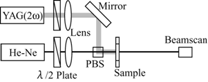
| | Figure 2. Schematic diagram of the experiments for a laser-induced lens in the DDLC films. PBS: polarized beam splitter. | | 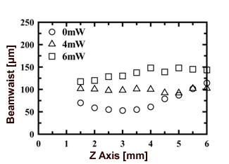
| | Figure 3. The diameter of an extraordinary wave (He-Ne laser) vs. propagation distance on varying pump beam intensities (frequency - doubled Nd:YAG laser). | Analysis In this study, we used 3-dimensional heat-conduction analysis to analyze the refractive index distribution in the laser-induced LC lens caused by the photothermal effect. The result of three-dimensional heat conduction analysis was used in the finite-difference time domain (FDTD) method. We analyzed the light wave propagation characteristics of two piece lens system by means of the FDTD method. Furthermore, we determined the change in a beam waist in a z-direction using diffraction theory. Three-Dimensional Heat Conduction Analysis Analysis by three-dimensional heat conduction was performed by using the finite-element method, as shown in Figure 4. The three-dimensional heat conduction equation in the steady state is given as: 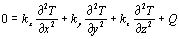 (1) (1)
where Q is the heat source in the media, which is supplied from the laser beam. The proportional factor ki ( i = x, y, z ) is known as the thermal conductivity. In order to solve Eq.1 analytically for the geometry described in Figure 4, we use the finite-element method under the following boundary conditions: 1. The temperature at the surface of the glass substrates is equal to room temperature. 2. -kLC (∂TLC / ∂n )B = -kGL (∂TGL / ∂n )B at the interface between the DDLC and the glass. 3. (TLC)B = (TGL)B at the interface between the DDLC and the glass. The heat source generated by the laser absorption and Gaussian transverse profile propagating into the DDLC film is expressed as: 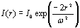 (2) (2)
where ω is the beam waist and I0 is peak intensity. | 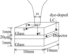
| | Figure 4. Geometry of 3-dimensional heat-conduction analysis. | Figure 5 shows the result of three-dimensional heat conduction analysis on varying pump beam intensity. This refractive index distribution is distribution of x-axis direction in point [(y,z)=(0,6)] that refractive index change is the largest in a sample. Because pump beam polarization was extraordinary, refractive index change was negative distribution. If pump beam intensity becomes high, a refractive index change becomes large, and a peak of refractive index becomes small. The calculated refractive index distribution was used in ray-matrix calculation and the finite-difference time domain method. | 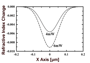
| | Figure 5. Calculated spatial distributions of the extraordinary refractive index change with variation of the pump-beam intensity in the x-axis direction at y=0 and z=6 [μm]. The thickness of the 5CB/DR9 film was 20μm and the dye concentration was 0.8wt%. | FDTD Method The incident light wave of the electric field is a standardized 2-dimensional Gaussian beam:  (3) (3)
where ω is determined based on the 1/e2 of field intensity. The beam waist was set so that the intensity distribution became 115 μm. We show an analysis area of the FDTD method in Figure 6. The FDTD method was used with an algorithm of Yee. We analyzed this measurement of the TE wave. | 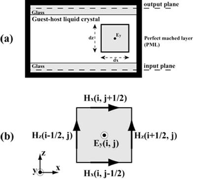
| | Figure 6. (a) The area of the computation space used in the FDTD method. (b) Yee cell used to fill the computational space. | Light-wave propagation is governed by Maxwell's equations: From the refractive index distribution of the LC that is the uniaxis anisotropic atmosphere, the dielectric constant was calculated by Eq.5 and used for the FDTD method:  (7) (7)
Because the system of measurement was a two-piece lens system, we set three-analysis areas, each with an [air - dummy lens - air – glass] area, a [glass - LC – glass] area, and a [glass – air] area. The focal distance and the beam waist of each dummy lens were 3 cm and 52 μm, respectively. The incident wave of the next area is the electric field distribution of output of the current area. In this analysis, we assumed that there was no in bound reflection for each area. The analysis conditions are listed in Table 1. Table 1. Simulation parameters used in the FDTD method. | | | Cell size, Δx=Δz | 40nm | | Cell number of x axis | 6500 260μm | | Cell number of z axis | 800 32μm | | Time step, Δt | 0.9×10⁻¹⁶ sec | | Thickness of PML slabs (cell number) | 40 | | Wave length | 632.8nm | | Beamwasit (He-Ne laser) | 115μm | Far Field Pattern Because it was a purpose in this study to analyze light propagation characteristics, we calculated the electric field strength distribution in a far field. However, as is already well known, the FDTD method requires great computer hardware capacity. Because carrying out the computation directly in a space of this size was impossible, we used diffraction theory to determine the electric field intensity distribution of the far field. The data-handling procedures were as follows: 1. The results were obtained using the FDTD method in the plane of z=z0. Note that this has a real value. 2. Fast Fourier transforming (FFT) Ey (x0, t) was done in a time domain, and its first order coefficients were taken to convert Ey (x0, t) into the complex amplitude: 3. Ẽy(xo)=FFTt[Ey(xo,t)] (8) where Ẽy(xo) is a complex value. 4. The amplitude and angle of the electric field were obtained with the time domain FFT in the observation plane. The far field pattern was obtained using Fraunhofer diffraction calculations. The diffraction geometry is shown in Figure 7. 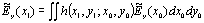 (9) (9)
Where: | 
| (10) | | 
| (11) | 5. The intensity profile in z=z1 was obtained:  (12) (12)
| 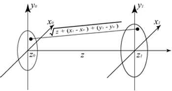
| | Figure 7. Diffraction geometry. | Results and Discussion Figure 8 shows a change of the beam waist provided by the analysis in which a measurement result and the FDTD method were used. A symbol is a measurement result, and the pump-beam intensities were 0, 4, and 6mW. A line is an analysis result of the FDTD method and the diffraction calculation. The refractive index change in the DDLC was determined in order to analyze a measurement result of each pump-beam intensity. As a result, an analysis result was satisfied when the refractive index distribution shown in Figure 9 was formed. However, this refractive index distribution was different from the refractive index distribution obtained by heat conduction analysis. | 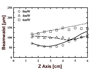
| | Figure 8. Beam waist and focal point (z axis) on varying the pump-beam power. Symbol and line represent the experimental and the diffraction theory FDTD method results, respectively. | | 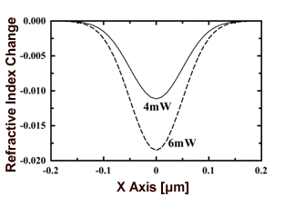
| | Figure 9. The refractive index change obtained by the FDTD method. | The refractive index difference was of the order of 10-3. A refractive index change is mainly caused by the beam waist and the intensity of the pump-beam at room temperature and within the temperature variation of the refractive index of the liquid crystal in this study. However, we think that the influence of this refractive index change was small because the beam waist, pump-beam intensity and room temperature were measurement conditions. Thus, we looked at the temperature variations of the refractive index of LC and considered the properties of the refractive index distribution that was obtained using the FDTD method. It is a method to compare the FDTD method result with the wedge method result. The temperature variation of the refractive index which we used in heat conduction analysis was measured by the wedge method. The temperature variation of the refractive index was calculated: | 
| (13) | | 
| (14) | where Ti (i=1,2,3,4) is the temperature coefficient, tr is the temperature of radius r, and n0 and t0 are the refractive index and the temperature in center of the refractive distribution, respectively. Figure 10 shows the temperature variation of the refractive index of liquid crystal. As shown in Figure 10, because there was no difference between the two temperature variations of the refractive index, we believe that the result of the refractive index distribution provided by the FDTD method is correct. | 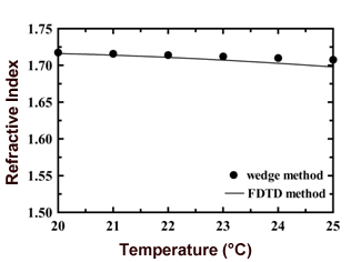
| | Figure 10. Temperature variation of the refractive index in the nematic liquid crystal. (●) wedge method (-) FDTD method. | Conclusion In this paper, we examined the effectiveness of the FDTD method for a liquid-crystal device. We analyzed the light propagation characteristics of the laser-induced LC lens formed by the photothermal effect that is the most basic in non-linear optics effect. We calculated the temperature distribution formed by a pump-beam in the LC layer by three-dimensional heat conduction analysis and obtained the refractive index distribution. The refractive index distribution was used to analyze the light propagation characteristics in the LC layer for the FDTD method. Furthermore, we did a Fast Fourier Transform of the electric field amplitude distribution of the FDTD analysis results in order to calculate a beam waist in a far field. We calculated the field strength distribution by diffraction theory. As a result, we identified a measurement result and showed the effectiveness of the FDTD method. References 1. T. Morisaki and H. Ono, “Analysis of the Laser-Induced Lens Generated in Guest-Host Liquid crystals,” IEICE, C, J87-C (2004) 132-140. 2. T. Morisaki and H. Ono, “Effects of Polarization on light propagation in laser-induced lens in guest host liquid crystals,” J. Appl. Phys., 95 (2004) 3279-3284. 3. S. D. Durbin, S. M. Arakelian and Y.R. Shen, “ Laser-induced diffraction pattern formation in defocusing liquid media,” Opt. Lett., 6 (1981) 411-413. 4. C. Khoo, J. Y. Hou, T. H. Liu, P.Y. Yan, R. R. Michael and G. M. Finn, “Transverse self-phase modulation and bistability in the transmission of a laser beam through a nonlinear thin film,” J. Opt. Soc. Am., B4, (1987) 886-891. 5. H. Ono and Y. Harato, “Characteristics of photothermal effects in guest-host liquid crystals by heat-conduction analysis,” J. Opt. Soc. Am., B 16 (1999) 2195. 6. H. Ono and K. Shibata, “Simultaneous determination of anisotropic thermal conductivities of liquid crystals by means of a photothermal self-diffracting technique,” J. Phys. D, Appl. Phys., 33 (2000) 137-140. 7. T. Uno, “Finite Difference Time Domain Method for Electro magnetic Field”, CORONA PUBLISHING CO., LTD, (1998) 8. Emmanouil E. Kriezis and Steve J. Elston, “Light wave propagation in liquid crystal displays by the 2-D finite-difference time-domain method,” Opt. Commun., 177 (2000) 69-77. 9. H. Ichikawa and Y. Sugimoto , “Electromagnetic numerical characterisation of a microfresnel lens of millimeter size for a CWDM device,” Opt. Commun., 234 (2004) 71. 10. Terman, F. E., Introduction to Fourier Optics (McGraw-Hill), 1968. Contact Details |