|
TiO2 has been widely used as paint and as a raw material for dielectric composites. Recently TiO2 has been attracted a lot of attention as a photocatalyst and a semiconductor electrode for dye-sensitized solar cells [1, 2]. Although TiO2 powder with high dispersibility is desired for the application to paints and as raw material, solid TiO2 like ceramic or film is much more convenient because of easy handling for photocatalysts and electrodes. Thin film is superior than ceramic for such use even if sufficient surface area can be obtained. There are various methods of forming thin films: sol-gel method, chemical vapor deposition, aerosol deposition method and sputtering method. The sol-gel method is widely used for fabricating films with high specific surface area [3]. The sputtering method forms dense and adhered films, but it is difficult to obtain porous films. The purpose of this work is to form a porous film from TiO2/ZnO composite films through a tripole magnetron sputtering and a succeeding ZnO dissolution processes. This method is based on the fact that acid and alkali preferentially dissolve ZnO. The tripole magnetron sputtering apparatus can control erosion area of a target (outside and inside) by changing the coil current of the controllable pole, which can produce either solid solution films or graded films when a target consisting of different materials in inside and outside is used.
Experimental Procedure
Two types of films were prepared; TiO2/ZnO single layer and ZnO-(TiO2/ZnO)-TiO2 triple layer on glass substrates (Corning #7059) shown in Figure 1 were deposited by a tripole magnetron sputtering apparatus. Ti and Zn plates were arranged inside and outside on the target, respectively, and the erosion area was switched from inner to outer of the target by changing the coil current of the controllable pole. The desired composition of the films was adjusted by changing the sputtering time of each area. Each sputtering time [s] of inside and outside (denoted by cycle ratio) for TiO2/ZnO composite films was set to 6/1 or 10/1. Total sputtering time of single layer was 20 h which made TiO2/ZnO film with thickness of about 1 μm. In the case of triple layer, the sputtering time of each layer, top ZnO layer, TiO2/ZnO layer and bottom TiO2 was 3 h, 15 h and 6 h, and thickness of each layer became 0.2, 0.8 and 0.2 μm respectively. Oxygen gas of 99.99% was introduced during the sputtering and it was carried out, keeping the substrate temperature at 200oC. ZnO was dissolved by using acetic acid of pH 4.5. Crystal structure and composition of the films before and after ZnO dissolution were evaluated by X-ray diffraction (XRD; Rigaku, RINT2200V/PC-SV), and microstructure was observed by field emission scanning electron microscope (FE-SEM: Hitachi, S-4100). Photocatalytic activity of the films was confirmed through decomposition of methylene blue solution, under UV light irradiation. The optical transmission spectrum of methylen blue was measured every 1 h by spectrometry (JASCO Co. Ltd. UBEST-55). A high pressure mercury lamp (1000 V) was used as a UV source.
Results and Discussion
Two types of thin films illustrated in Figure 1 were deposited by Ti-Zn alternative sputtering using a tripole magnetron sputtering apparatus. Figure 2 shows XRD patterns of single and triple layer films before and after immersing in acetic acid of pH 4.5. Rutile TiO2 and anatase TiO2 were obtained in both types of films, however, Bragg angle, 2θ and intensity of the peaks were different from each other. Neither ZnO phase nor compounds consist of Ti and Zn could be confirmed in TiO2/ZnO layer deposited by Ti-Zn alternative sputtering, even when Zn content (outer sputtering time) increased; the expected TiO2/ZnO composite could not be created. It is considered that Zn formed a solid solution with TiO2, and amorphous ZnO may be formed due to the low particle energy sputtered from outer target or the shortness of sputtering time. In the case of single layer, although both rutile and anatase TiO2 were formed when outer sputtering time was short (10/1), only weak rutile TiO2 peaks were confirmed when the cycle ratio was 6/1. Under these conditions only using Ti plates, anatase TiO2 was preferentially formed, even though deposition speed and crystallinity of films became low because the outer sputtering energy is lower than the inner [4, 5]. This result is different from the tendency of TiO2 films without Zn, indicating that the film structure became amorphous or rutile TiO2 that is high temperature phase of TiO2. Such structures became stable by forming solid solution with Zn as outer sputtering time increased. After dissolution, the composition of the single layer did not show any change.
Figure 1. Schematic illustration of sputtered film structure.
In the case of triple layer films, ZnO of the top layer, rutile and anatase TiO2 were observed in XRD pattern before immersed in acetic acid, while ZnO peaks disappeared and only TiO2 phases remained after the immersion. Peaks of anatase TiO2 appeared more significantly than the single layer film when the cycle ratio was 6/1. These peaks seem to be not TiO2 deposited under TiO2/ZnO layer but the crystal structure of TiO2 including Zn that was influenced by the crystal structure of TiO2 deposited on substrate. From the results, a triple layer film with cycle ratio of 6/1 including anatase TiO2 that has high photocatalytic activity is expected for photocatalyst.
(a) XRD pattern of single layer before and after dissolution
(b) XRD pattern of triple layer before and after dissolution.
Figure 2. XRD pattern of sputtered films before and after ZnO dissolution.
Figure 3 shows SEM images of sputtered film before and after immersion in acetic acid. Both single and triple layer films had dense and smooth surface before the immersion. Column diameter of triple layer film laminated with ZnO layer seemed to be larger than that of single film before ZnO dissolution. In the case of the triple film, texture of top ZnO layer was independent of the composition of TiO2/ZnO layer before the dissolution as can be seen from SEM images, however, appearance of film surface after the dissolution is quite different. The surface was gouged out as column perimeter was etched in the triple layer films with both cycle ratios of 6/1 and 10/1, and rough surface was obtained. However, the difference appeared in erosion area after ZnO dissolution: erosion area of 10/1 film was narrow, while 6/1 film was wide. This dissolution mechanism is considered as follows. During deposition, Zn moved and segregated at column perimeter with the aid of temperature of 200oC, and it is easy for segregated Zn to incorporate with the top ZnO layer. The segregated Zn was also dissolved when top ZnO layer is dissolved by acetic acid. Segregation of Zn to column perimeter may occur easier in 6/1 film, because TiO2/ZnO layer with 6/1 contained Zn more than that with 10/1. Since Zn segregation decreased, erosion areas become small and narrow as in the film with cycle ratio of 10/1. From this result, it may be possible to control the erosion area of surface by changing composition of TiO2/ZnO in the case of triple layer.
In the case of single film, any significant difference in the surface was not observed before and after the dissolution and some elongative particles appeared. It is considered that the behavior of Zn in single layer films without top ZnO layer is similar as in the triple layer, however, the surface structure was not markedly changed as in the triple layer film because Zn could not segregate to the column perimeter near surface and dissolution did not progress without ZnO which works as a core of Zn condensation and dissolution. ZnO top layer enhanced dissolution from TiO2/ZnO layer and then rougher surface can be obtained.
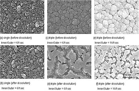
Figure 3. SEM photographs of films before and after ZnO dissolution.
Typical transmission spectra of methylen blue after the photocatalytic decomposition by single and triple layer films is shown in Figure 4. A transmission spectrum of methylen blue decomposed by TiO2 film that was formed only by inner sputtering is also shown for comparison in Figure 4. Figure 5 shows transmittance variation of methylene blue in every hour in the wavelength of 664 nm. As the decomposition progressed, transmittance of methylen blue at about 600 and 660 nm in the wavelength became high, however, there were some differences of decomposition rate in each sample. Even though single layer films did not show any difference in microstructure before and after the dissolution judging from SEM images, the decomposition activity by the film after dissolution clearly improved. The transmittance changing ratio of the 6/1 films without (before) the dissolution was the smallest and the activity was the lowest, because amount of TiO2 with high phtocatalytic activity at the surface decreased by ZnO. The single and triple films after the dissolution indicated more improved photocatalytic activity than the TiO2 film even without clear anatase TiO2 phase. It may be resulted from the fact that immersing in acetic acid might make the surface rough microscopically, although increase in surface area could not be confirmed by SEM observation. The triple layer film formed at cycle ratio of 6/1 after ZnO dissolution exhibited the highest photocatalytic activity in this work; transmittance of the triple layer film with 6/1 at 664 nm in the wavelength varied from 19.7% to 78.8% after 4 h, while the transmittance of TiO2 film from 20.0% to 63.2%. This is due to increase in surface area as shown in SEM image. Decomposition activity of the triple layer film with cycle ratio of 10/1, where the surface area increased clearly by the dissolution as seen from SEM observation, was about the same as that of single layer film with 6/1. It is considered that eroded portion was too narrow and small for UV light to enter inside of corroded parts (pore). More detailed analysis about the role of ZnO top layer and amount of surface increased by the dissolution are now under process.
Figure 4. Transmission spectra of methylene blue after decomposition by using sputtered films.
Figure 5. The variation of transmittance of methylene blue in every hour at the wavelength of 664 nm.
Although usual sputtering method can produce only dense films with low specific surface area, it was shown that surface area could be increased in the films by the dissolution of a dummy material, e.g. ZnO from the TiO2/ZnO films. Although acetic acid was used for the dissolution in this work, photo dissolution can be used in order to dissolve ZnO from the TiO2/ZnO layer. Photocatalytic activity of triple layer film with dissolution treatment improved significantly compared with TiO2 film. Optimizing the sputtering condition upon deposition of TiO2/ZnO layer can vary the erosion behavior. Further, photocatalytic activity can be improved by controlling erosion size so that UV light can enter. Since the tripole magnetron sputtering apparatus can form functionally graded layer structures, a better photocatalytic film could be formed using the function of this equipment. If the surface area is larger, the triple layer after the dissolution can be applied as a semiconductor electrode for dye-sensitized solar cells.
Conclusions
TiO2 films including Zn were deposited by Ti-Zn alternative sputtering using a tripole magnetron sputtering apparatus. The surface was gouged out by dissolution of ZnO top layer and TiO2/ZnO at column perimeter was etched in ZnO-(TiO2/ZnO)-TiO2 triple layer films, and rough surface films possessing larger surface areas than TiO2 films were obtained. The films indicated higher photocatalytic activity through decomposition of methylene blue.
Acknowledgements
This research was partially supported by the Ministry of Education, Science, Sports and Culture, Grant-in-Aid for Young Scientists (A), 15686030, 2003.
References
1. Akira Fujishima, “Present Situation in TiO2 Photocatalysis”, Bull. Ceram. Soc. Jpn., 39 (2004) 499-503.
2. Michael Grätzel, “Photoelectrochemical Cell”, Nature, 414 (2001) 338-344.
3. Kazumi Kato, “Design and Functions of Porous TiO2 Thin Coatings Through a Novel Process”, Materials Integration, 12 (1999) 35-40.
4. Satoru Miyairi, Noriko Bamba and Tatsuo Fukami, “The Technical Report of The Proceeding of The Institute of Electronics”, Information and communication Engineers, CMP98-114 (1998) 7-14.
5. Tatsuo Fukami, Tomohiko Naruoka, Tomoaki Momose and Noriko Bamba, “'Effects of sputtering atmosphere oxygen pressure on photocatalytic phenomena in anatase films “, Jpn. J. Appl. Phys., 41 (2002) L794 - L796.
|