| There are a number of ‘rules of thumb’ and formulae, developed by manufacturers, which are useful in the design of a seal using reinforced rubbers: • The thinnest practicable gasket is best, greater thicknesses increase both stress relaxation and the amount of material exposed to the environment • Inside dimensions of the gasket and the flange should be the same • Clean cut edges are essential as ragged edges always favour leakage • The lateral compliance of a gasket (proportional to its thickness and, inversely proportional to the area and shear modulus) can be helpful in preventing fretting caused by vibration. Alternatively, dowels may be used to prevent relative lateral movement of the flanges. • Presoaking of gaskets has been shown experimentally to be undesirable. Gasket manufacturers have empirical formulae for joint design. These were developed for asbestos reinforced rubber and the use of aramid or other reinforcing fibres requires different values for some factors. The following expression is suggested as a starting point, S=Y+mP+PA/A' where S is the minimum assembly stress, Y is the minimum stress needed to force the gasket into the flange surface roughness and consolidate its bulk (typical values are 14MPa for liquid tight joints or 28MPa for gas tight joints), P is the internal fluid pressure, A is the enclosed area and A' is the gasket cross sectional area. Thus mP is the residual stress in the gasket having to withstand the radial force generated by the internal pressure P (a typical value for m would be 1.1). and PA/A' is the force expressed as a stress on A' needed to contain P acting over A. After trials adjustments may be needed, particularly if the application involves any temperature cycling. Flange Fixation The choice of the number of bolts around the flange is usually dictated by the risk of flange distortion. Generally doubling their number will decrease bowing to one eighth. The diameter of the bolts, and the torque used in assembly, is dictated by the need to contain the pressure plus the excess stress for sealing estimated by the equation above. Gasket Width Gaskets resist leakage or blowout purely by frictional forces so the gasket width should be at least twice its thickness and the assembly stress as calculated in the equation above should be at least two times the internal pressure. Other Design Aspects Anti-friction treatments (such as graphite) applied to a gasket may cause problems, but by reducing adhesion they can make disassembly easier. Room temperature vulcanising (RTV) silicones can be useful as anti-adhesion supplements to gaskets, especially for damaged flanges, as well as serving as useful formed in place gaskets in their own right. Non-asbestos gaskets crush more readily than the asbestos-based variety and should not be subjected to a stress greater than 100MPa or so. Formed in Place Gaskets Many possibilities are now available including: • PTFE cord wound round bolts which exhibits high ‘cold flow’ under a load, even at room temperature. This forces it into the threads, sealing them, but the joint has low blowout pressure • Sealant beads, usually of silicone rubber. which are useful for sealing lubricating oils but not fuels • Foamed epoxy resins are generally good for sealing against air, water, oils and conventional fuels to about 120°C but useless against alcohols • PVC plastisols gelled by heat have a similar range but above 70°C there is a risk of corrosion, especially for aluminium surfaces Anaerobic Resins Anaerobic resins which cure in the absence of oxygen provide the most useful ‘liquid gaskets’. Perhaps more familiar as 'superglue' these materials are increasingly used for automotive and other applications (e.g. gearboxes), giving very stiff joints with many bolts, but are not suitable for pressed steel covers or surfaces that tend to move laterally. They are stiff in shear but are not intended to be ‘adhesives’. Specialised types exist which can give service up to 180°C. Static Joint Design with ‘0’ Rings and Other Automatic Seals As an alternative to gaskets, static flange joints may be sealed using an elastomeric ‘O’ ring in a machined recess (figure 1). In these configurations the sealing action is said to be ‘automatic’ since the action of the pressure differential itself ‘energises’ the seal to generate the sealing pressure. | 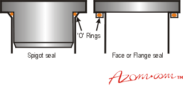
| | Figure 1. Static Seals with ‘O’ rings. | The flange faces should be fully in contact after assembly, with a compression of about 20% applied to the ‘O’ ring. This determines the relationship between the depth of the recess and the ring cross-section. The width of the recess should be sufficient to accommodate the thermal expansion of the ‘O’ ring since the rubber can be regarded as incompressible and the coefficient of thermal expansion of most rubbers is twenty times that of steel. Automatic face seals are also manufactured with various non-circular cross sections, including U-shaped sections with the open end of the U facing the high pressure side. If the faces tend to separate, for example under the action of a pulsating pressure, it may be necessary to fit anti-extrusion rings on the low pressure side, Figure 2. These rings must have a much higher modulus than the elastomeric ring, but elasticity is less important. Suitable materials are phosphor bronze or plastics such as nylon or filled PTFE. | 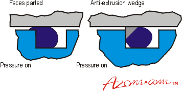
| | Figure 2. Use of anti-extrusion wedges. | Pipe Seals Softer rubbers, such as lightly filled natural rubber, come into their own against very rough surfaces such as clay pipes. Natural rubber also has the key property of low rate of stress relaxation, and case histories of a service life of 100 years exist for sewer pipe seals. |