| The conventional brake equipment of a bogie of a high speed railway coach consists of four brake disks and the associated calipers, hand brake and electromagnetic track brake systems (figure 1). As that amounts to about 20% of the total bogie mass, it is worth considering opportunities for weight reduction. This made the German company Sab Wabco BSI think about using light alloys for railway brake equipment in 1992. As the mass of the brake disks was 460 kg on a single axle, the disk was an obvious target for weight reduction. Disk weight was reduced from 115 kg for an SG iron disk to 65 kg for an Al-MMC disk. However, as the price of the MMC material is relatively high was considered best to restrict the use of MMC to the most important functional areas, which are the friction surfaces. | 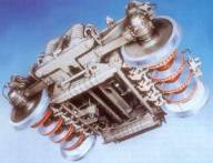
| | Figure 1. A conventional bogie for a high speed railway carriage. | Thermal Characteristics The thermal characteristics of aluminium alloys show great advantages compared to those of iron alloys. The specific heat capacity is 1.7 times higher than that of the usual SG iron and the thermal conductivity is 5.3 times that of SG iron. The maximum application temperature for the aluminium is only about 400°C compared to approximately 500 °C for SG iron with special pad material. However, it can be used as a brake disk material because typically the maximum average friction face temperatures with railway applications are only about 350°C. At these temperatures, the yield strength (a nominal 153 NM2 at 260°C) is sufficient to bear the service loads caused by the braking forces and inertia. The high thermal conductivity, together with the low modulus of elasticity, assist in achieving low stresses in the case of thermal inputs caused by friction braking. The thermographic records taken on a SG iron disk and an Al-MMC disk during the same brake load (figure 2) reveal the temperature equalisation in the friction surface. This temperature equalisation also reduces the stress gradients caused by ‘hot spots’ on the friction surface. | 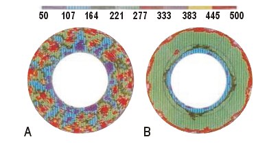
| | Figure 2. Thermographic records for (a) an SG iron brake disk and (b) an Al-MMC disk under the same load. | Brake Disk Wear Characteristics At first it was expected that excessive wear would preclude the use of aluminium disks for railway applications. This judgement was revised after the first full scale dynamometer tests with SiC particle reinforced Al-MMC brake disks were carried out. Because of the reinforcement by the SiC particles, the wear behaviour of the Al-MMC proved to be surprisingly lower than the wear rates of existing standard friction ring materials such as grey cast iron and SG iron. The wear rates attained in field tests, over distances of 1.2 x l06km, gave an overall predicted wear life of more than 15 years. A cheaper alternative to the MMC is LM30 aluminium alloy. This proved usable and achieved similar friction coefficients as the MMC, but the wear rate was twice to three times as high. Brake Pad Wear Characteristics Pad wear also proved to be much less on the Al-MMC disks, being about one half to two thirds of the wear obtained with iron materials. The low wear rates of disks and pads should reduce the life cycle costs of the brake and give a further commercial advantage to the operator, as the vehicle maintenance costs are also reduced. Environmental Considerations An additional advantage of using an Al-MMC alloy for railway brake disks is that it is much less prone to squealing than iron materials. This is becoming more important as railways are having to operate under increasingly tighter environmental controls. The odour of brake pad material often emitted after heavy braking was also remarkably reduced, because the maximum friction face temperatures are lower compared to SG iron disks under the same brake load, due to the increased thermal conductivity. Disadvantages of the MMCs One disadvantage of the SiC reinforcement, is a reduction in elongation to 0.3%, comparable to grey cast iron. Crack propagation is also relatively high. These problems initiated research into design principles and production methods for tougher brake disks. In principle, despite their advantages, the reduced ductility and elevated crack growth behaviour of SiC particulate reinforced cast alloys can lead to rapidly growing fatigue cracks due to shear stresses. This is particularly relevant for friction rings of disk brakes, which have to withstand thermal alternating loads. These thermal loads create radial cracks that continue to the inner regions of the friction ring and may result in a sudden failure. Normally, these cracks can easily propagate in particulate reinforced materials, because the particles in the eutectic support both crack formation and propagation. Alternatives To combine the advantages of high thermal conductivity with improved ductility, a high strength Al-alloy should be used, which offers good mechanical properties even after extended thermal loads. The cast metal A356 was chosen for this purpose. Locally reinforced friction rings with ductile carrier body can be manufactured by different processes, for instance: • infiltration of ceramic preforms • compound casting • multi-pouring (sandwich-casting) • plasma-spraying All these solutions aim to keep the wear of the friction ring as low as possible, while ensuring ductile fracture behaviour in the axle-mounting regions. They also offer economic manufacturing alternatives to the existing materials. Three of these solutions have been investigated in a joint research and development project between Aachen University, Thyssen Guss AG and Sab Wabco BSI. A prototype disk brake rotor with ICE-1 ventilation has been designed. Figure 3 shows cross sections of prototypes made by the three methods. | 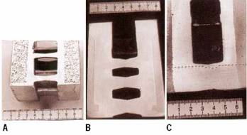
| | Figure 3. Cross sections of prototype brake disks made by (a) infiltration, (b) compound casting and (c) multi-pouring. | Ceramic Preform Infiltration Infiltration techniques like the squeeze-casting process are well known in the field of short-fibre penetration, and they need highly mechanised, expensive equipment. For this reason these techniques cannot be adopted to disk brakes for rail vehicles. Reticulated ceramic foams, which are usually used for the infiltration by molten masses, offer the possibility to create locally reinforced cast parts by the low-pressure process. A metallostatic pressure of about 1.3 bar is adequate to overcome the resistance against flow and to press the melt into the preform. Coating the ceramic with a reactive metallic element improves the wettability and leads to a reduced metallostatic pressure and resistance against flow. Even matrix inhomogenities between the macroscopic and microscopic porosity can be eliminated. The thermal conductivity and the specific heat capacity of these composites can be compared with SiC-particulate reinforced cast alloys and is affected by the A356-alloy and the ceramic. The wear resistance is only conferred by the ceramic foam. Compound Casting For compound casting, pre-manufactured wear resistant inlays made of a SiC-PMMC are preheated, fixed inside a mould cavity and then overcast with the A356-alloy. For this technique any casting processes can be used if it offers an extended local solidification time. It is usual to cast a high melting alloy on a low melting alloy. When combining two Al alloys that have a similar solidification range it is difficult to heat up the inlay surface, because Al alloys need a significant heat to melt. Another problem is the tendency of liquid and solid Al alloys to oxidise, thus hindering the heat exchange and adequate fusion between the inlay and the melt. Fusion between the alloys is needed for most technical applications, and can be achieved by correct preheating and pouring temperatures and also an intelligent design of the contact surface of the inlays. The local volume ratio between the melt and the solid phase plays a major role in this. To determine the optimum contact surface design, numerical simulations tools such as those used in the foundry industry are very helpful. Although the inlays are covered with oxide layers to begin with, a good bond can be achieved in most regions. During the fusion process, the surroundings of the oxide layers are heated up almost to melting temperature and liquefy. The oxides mix with the liquid phases or are dissolved. The resulting bond along the radius of an inlay shows defects only close to the inner and outer radius. Multi-Pouring The multi-pouring process creates a locally reinforced rotor by time consecutive casting. Expensive and energy-consuming manufacturing and preheating of inlays can be avoided. Additionally, the process window is enlarged, because the mixing of liquid phases always leads to proper fusion and the amount of expensive PMMC is reduced to a minimum. The shape of the interface between the solidifying alloys are influenced by easily controllable casting parameters. Basically, interface morphology can be described as ‘smooth’ or ‘rough’. The preferred morphology depends on the application and the load on the part. If tensile strength or flat functional layers with only a minimum of material consumption are needed, a smooth interface should be chosen. If a gradient of thermal expansion is required, a rough morphology is better. The cyclical transformation of kinetic energy into braking heat leads to an alternating tensile/compressive load, which can lead to radial cracks on the friction ring surface. With increasing cycle numbers these cracks propagate to the centre of the disk. Most materials show an increase in crack propagation velocity with increasing stress intensity. SiC-PMMCs already fail at low stress intensities, with high crack propagation velocity. LM30 is more insensitive to crack growth. By combining the SiC-PMMC with A356 in the multi-pouring process, the crack growth velocity can be decreased, despite increasing stress intensity. The sandwich casting composite shows significantly lower crack propagation compared with LM30 and the pure SiC-PMMC at the same stress intensity. The multi-pouring composite can stand significantly more cycles and offers the possibility to extend the maintenance interval or increase the service life of the part. Summary Disk Production Methods Locally reinforced brake disks made by any of the above three processes are suitable for brake applications. However, the specific friction ring and pad wear of each is different (fig 4). The SiC-PMMC braking surface is unbeatable compared with ferrous materials and other alternatives like infiltration composites and plasma-sprayed disks as far as the friction ring wear is concerned, regardless of how the SiC-PMMC braking surface was made (compound casting, multi-pouring or by conventional casting of the pure alloy itself). | 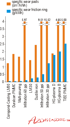
| | Figure 4. Specific wear of the friction ring and the brake pad material of the prototype disks tested under realistic loads. | Brake Pad Wear To overcome the significant pad wear that occurs with the infiltration composites, further development of the pad material is required, but this involves high development costs. Thermal Characteristics The braking temperature measured 1 mm below the braking surface was lower than that in conventional SiC-PMMCs for all locally reinforced disks, as long as fusion had occurred. Economic Issues In the disk brake sector, MMCs concur with extremely cost efficient ferrous materials. The composite materials can only succeed by offering better properties at lower costs. The locally optimised disks offer a first step towards meeting this aim. Savings of about 52% of the material costs (finished part) with enhanced machinability are possible. |