Jun 19 2001
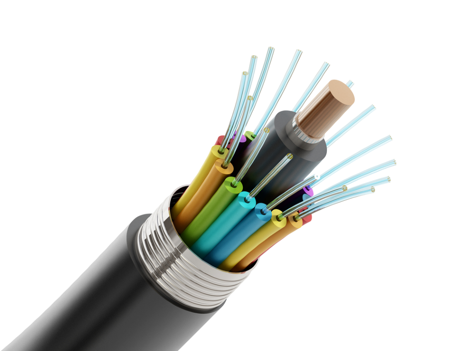
Image Credit: cigdem/Shutterstock.com
This article was updated on 5th Feb by Clare Kiernan.
Since the turn of the century, the explosion of information technology has created a requirement for large quantities of high-quality fiber optic cables, which are thousands of kilometers long and 100 microns thick.
Production of Optic Fibres
Fibers are produced by placing a silica duplex preform at the top of a furnace. The furnace is heated up to about 2,300 °C and the fiber is rapidly drawn from the preform through the furnace. The temperature must be maintained within ±2 °C, to produce the fiber at a uniform thickness. The furnace materials and conditions are critical, and any degradation can result in the damage and breakage of the fiber.
Susceptors
Stanelco Products has been producing induction heating equipment for a range of industries for many years. The company's major market is supplying induction generators and furnace equipment to fiber manufacturers.
The company has worked with AEA Technology to produce the precision ceramic tubes that are used within the furnace as susceptor elements - the heating elements within the furnace. A radio frequency (RF) field is applied, causing the molecules in the susceptor tube to vibrate, thus generating heat. These susceptor elements are made using a plasma spraying technique that AEA Technology had refined for many years.
There are only a few companies in the world that supply plasma-sprayed zirconia tubes for use by optical fiber manufacturers. The traditional way of making fiber optic susceptor tubes for drawing furnaces is to use slip-cast coatings. However, the use of plasma spray technology allows the production of fiber optic cables at much higher tolerances.
Plasma Spraying
Plasma spraying is primarily used for depositing surface coatings. It is one of a family of techniques known generically as ‘thermal spraying’. Here, the material to be sprayed is rapidly heated until most of it is molten. It is then projected at high speed onto a suitably prepared surface where the desired coating is given.
The Energy Source
In the plasma production process, the heat source is an electric arc struck between two electrodes, and the anode serves as a nozzle. The process is designed so that the arc is constricted and stabilized within the nozzle. Temperatures up to 20,000 °C cause the plasma to be ejected with velocities of several hundred meters per second.
The arc plasma is a source of thermal and kinetic energy to entrained material. Most devices use nitrogen, argon, or helium as the plasma (often with small additions of hydrogen) and operate at power levels between 20 kW-80 kW.
The Coating Material
The coating material, in powder form, is injected into the plasma at a position determined mainly by its melting point. Because of the high temperature, the inert nature of the plasma, and because the particles only exist for less than one second, almost any material can be sprayed. However, it must melt without significant dissociation or evaporation. Many metals, ceramics, and some plastics can be sprayed.
The Substrate
Plasma spraying is a cold process. It is, therefore, possible to coat a wide range of materials including those with low melting points, with minimal risk of oxidation or distortion. Substrate preparation usually consists of degreasing and surface roughening, for example by grit blasting, to increase the effective area.
Deposition Characteristics
Plasma spraying is a rapid deposition process. Coatings range from 100 microns to several millimeters thick. The technique can, therefore, be used to manufacture products from materials that are difficult to work or have geometries unsuitable for conventional fabrication routes. Beneficially, the material can be processed without binders. It is simply built up as a coating on a suitable mandrel, which is subsequently removed.
Zirconia Susceptors
Experience suggests that plasma-sprayed ceramic susceptors should ideally be made from zirconia. This is one of the few materials that does not melt at 2,300 °C. AEA Technology’s tubes are high purity, dimensionally precise, and designed to withstand thermal shock. The risk of fiber breakage is therefore low, allowing manufacturers to draw longer lengths of fine tolerance fiber.
Early Zirconia Susceptors
Early zirconia susceptors for induction generators were slip cast and fired. These tended to crack during operation and to split particles from their inner walls. Cracking and particle shedding was caused by cooling down through the transformation temperature to the monolithic form. At transformation, volume changes of 5-9% produced stress cracking and loosened fragments of zirconia from the walls.
Stabilized Zirconias
Stabilizing the zirconia with yttria produced a cubic crystal formation. Even with repeated cycling to its melting point, stabilized zirconia retains its tetragonal polycrystalline form and has a linear thermal expansion curve.
Control of the manufacturing process during zirconia precipitation is essential to obtain the correct amount and distribution of the stabilizer. During calcination, the size of the powder particles must be controlled. Stabilizer distribution must be uniform and powder particle size minimized to produce a microstructure that is resistant to thermal shock.
Further Developments
Further prototype susceptors were produced with a controlled stabilizer content. These susceptors had optimal electrical conductivity, proved easier to start from cold and gave improved efficiency during long production runs.
The latest design is a plasma-sprayed, twin-walled susceptor. Plasma spraying produces a lamellar microstructure, which has superior properties to that produced by slip casting. The layered structure accommodates the effects of temperature change more readily, increasing its resistance to thermal stress.
Most firms buy powder that is designed to produce coatings on components. However, the material requirements for the optimum production of near net shapes differed considerably. Consequently, sol-gel precipitation processes were used to process the powders and produce feed materials with the desired properties.
Sol-Gel Processed Powders
This process can be used to prepare ceramic powders of controlled particle size, shape, density and composition. This avoids the lengthy processes of comminution and sieving that are normally required to obtain optimum powder characteristics for ceramic fabrication. The sol-gel process is an intermediate stage. It involves the production of a gel of hydrous oxides or hydroxides of colloidal dimensions.
Subsequent calcination leads to a loss of water and densification of the particles at lower temperatures than are required for conventional powders.
Dense, spherical powders of alumina and calcia stabilized zirconia have been prepared using the sol-gel precipitation process. The powders are very pure and range in size from 10 microns to 70 microns. They have excellent flow characteristics and are suitable for the deposition of reproducible coatings by plasma spraying.