|
Although the rate of adoption of composite materials in the gas turbine engine has not met the expectations of a decade ago, their superior specific strength and stiffness remain as tantalising as ever. Indeed, in the fiercely competitive marketplace the significant prizes to be won by successful exploitation of such qualities merit added impetus to such pursuits.
The challenge to realise applications of the advanced composite systems has increased in recent years by the sharper focus on cost reduction. The rate at which these materials are introduced will be governed by their cost effectiveness rather than their technical merits.
Use of PMCs in Modern Aeroengines
The use of polymer matrix composites (PMCs) in aerospace application dates from the early 40s, the large-scale carbon fibre production of the early 70s making them serious competitors with metals for complex lightweight structures. Complete airframes can now be produced in PMCs, and they are essential to modern helicopters. Temperature requirements limit their use in aeroengines, but most of the nacelle of a modern aero gas turbine is PMC, a component that accounts for around 25% of the weight and 20% of the cost of the power plant. Other PMC parts in current engines include fan blades, outlet guide vanes, bypass ducts, nose cone spinners, core engine fairings, annulus fillers and variable guide vane rings.
MMCs and CMCs for Aerospace Applications
Intensive research in industry and academia on ceramic and metal matrix composite (CMC and MMC) systems through the 80s, supported by major government funded research programmes such as IHPTET in the US, has delivered the first MMC and CMC components into demonstrator and development engines. Military applications of CMCs in the form of afterburner nozzle petals are close to production.
Why use Composites?
Until recently, the two major, inter-related, drivers for the application of composites in engines have been weight reduction and performance improvement. MMC compressor drums have the potential for 80% weight saving over a conventional disc and blade assembly and PMC components typically provide 20-30% weight saving. The primary advantage of CMCs, as well as bringing weight benefits, is the ability to operate uncooled at temperatures beyond the reach of metals. Cycle efficiency improvements, from reducing cooling air to turbine aerofoils and seals, lead to significant specific fuel consumption benefits. For example, the replacement of metal seals by advanced CMC technology would yield a saving of $250,000 on the Boeing 777 aircraft over 15 years. Applications in combustion chambers earn CMCs a ‘green ticket’, i.e. a redistribution of the reduction in cooling airflow contributes significantly to the control of harmful emissions.
In today’s fiercely competitive aeroengine market, the primary product discriminators are cost-driven. Typical cost savings of 20-30% delivered by PMCs in replacing incumbent metal parts, therefore, provide added incentive for wider application of these materials. With these impressive advantages on offer, it may seem difficult to understand why composite materials do not dominate the latest civil and military engines.
Evolution of the Gas Turbine engine
The aircraft gas turbine engine was developed initially for military applications in the 40s with the first civil applications following in the 50s. During the Cold War period military requirements drove the development of the technology and civil engines benefited from the spin off and consequent reduction in development costs. Today’s market is very different. Military markets, at best, are stabilising after a period of dramatic decline and development cycles for new products such as the EJ 200 engine for Eurofighter 2000 have been significantly extended in time. The civil market is highly competitive with the three main engine builders (General Electric, Pratt and Whitney and Rolls-Royce) battling for market share.
Continued growth in passenger traffic generates a huge potential market for civil air transport products. Currently the airlines are coming back into profit. With reducing returns on seat sales, however, they must acquire equipment at the lowest possible prices. Because of these factors, today’s primary product discriminators are cost-driven in terms of initial procurement cost and cost of ownership. New technology is essential to achieve the required performance targets, but it must now contribute to cost targets too.
Advances in Materials Technology
Materials technology is of fundamental importance to the gas turbine engine. The ultimate efficiency of the engine is limited by operating temperature and, consequently, it requires materials with high temperature capability. The incessant drive to reduce emissions is compounding this need. Engine weight is another important factor, impacting on fuel consumption and military aircraft agility, thus stimulating the demand for low-density materials.
Attributes of Successful Aerospace Composites
The attributes of composites provide a good match to these general requirements. In broad terms, there are four principal success factors required for a composite application:
- Overcoming the culture barrier in replacing incumbent metal components
- Having a suitable opportunity in an engine project
- Developing the whole range of relevant technologies
- Providing sufficient demonstration of that technology for confident service introduction.
Rolls-Royce Venture into Carbon Fibre Reinforced Composites
The introduction of carbon fibre in the 60s saw Rolls Royce’s first major exercise in incorporating composites into engines, with the Hyfil fan blade for the RB211. At that time, Rolls Royce’s confidence in using a relatively new and, in hindsight, unproven material for a major rotating component was based on the fact that it had a thorough understanding of the material at the laminate level. Lacking, however, was sufficient experience to translate that knowledge into the fan blade application within the timescale imposed by the RB211 programme. Problems with manufacturing repeatability and bird impact resistance eventually resulted in the switch to a titanium component. Events such as this are extremely costly. In a fiercely competitive marketplace, engine development costs need to be tightly controlled, and risks minimised to ensure profitability. This tends to drive a design culture that is predominantly evolutionary. In this environment, a change of material for a component from a familiar alloy to a composite will only occur when the metallic part has reached a limit in terms of weight and/or cost or temperature capability.
A good example of this evolutionary process is the way in which PMCs have been increasingly used in engine nacelles. Driven by the need to reduce weight in relation to existing aluminium designs, composites were first applied to relatively simple parts such as the RB211 524 cowl doors, fig 1. Applications spread progressively in this region of the engine to the extent that PMCs now dominate the nacelle. A logical extension of the technology has occurred in by-pass ducts for both military (General Electric F414) and civil (Rolls-Royce Tay) engines.
|
|
|
Figure 1. Composite cowl door for an RB211-524.
|
Introduction into New Engine Projects
Step change engine designs, which are the optimum vehicles to target for application of new materials technology, occur relatively infrequently. For example, both Rolls Royce’s Trent and General Electric’s GE90 were launched in the early 90s only after their previous engines, the RB211 524 and CF6, respectively, had served them well for over 15 years in their various marques. The reason that such vehicles provide excellent opportunities to increase composite penetration is that engine launch is preceded by a detailed development programme, the cost of which is spread across all components. Post-certification qualification of components in new materials on an ad hoc basis, by contrast, is prohibitively expensive.
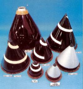
This issue is typified by the glass-reinforced epoxy fan nose spinner now used on all Rolls Royce civil engines (figure 2). Although this appears to be a relatively straightforward component in terms of materials and manufacturing process, entry into service and the realisation of the cost and weight benefits had to wait until the costs of the certification test programme (cyclic fatigue and bird impact) could be borne by the launch of the next variants of the RB211 engine.
|
|
|
Figure 2. Rolls-Royce fan nose spinners.
|
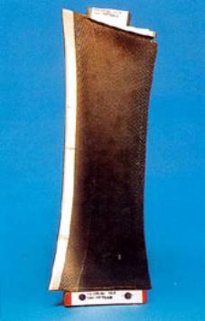
The use of carbon-fibre-reinforced epoxy fan outlet guide vanes is a more recent example of the need for an opportunity to secure a composite application, fig 3. Although proven in terms of materials and manufacturing process, and having survived limited engine exposure, this specific application awaits the launch of a new engine design to reap the potential cost and weight benefits. Further qualification testing to clear this component for service operation would include extensive strain gauge surveys under forward/reverse thrust and cross-wind loads followed by the standard 150 hour ‘modification approval’ engine test costing in excess of US$1.5million, obviously unjustifiable for this component alone.
|
|
|
Figure 3. A carbon fibre reinforced epoxy Trent fan outlet guide vane.
|
Composite Integration
Metals have been used in the aeroengine since its invention and, consequently, the associated technologies required for their integration into the engine, for example the designs of joints, methods of preventing corrosion and component lifing methodologies, are all very well established. Composite materials clearly do not share this luxury. Although some of the materials and manufacturing processes have been in place for nearly thirty years, the full suite of technologies needed for regular, successful applications is not yet in place. In fact, it is often the case that a potentially highly beneficial application cannot be attempted until specific ‘engine integration’ technologies have been delivered.
Future Composite Applications
Looking further into the future, one area of application that potentially yields the largest benefits in terms of cost and weight reduction is the large static structure located immediately behind the fan on a civil engine. Depending on the engine configuration, this component can carry a multiplicity of major structural loadings including the engine mass, the forward thrust, the reverse thrust on landing and the out of balance forces caused by the loss of a fan blade.
To cope with this arduous duty, it is essential that the composite component has at least equivalent integrity to its isotropic metallic equivalent. This means developing a full understanding of the application in terms of vibration characteristics, strength under static, fatigue and dynamic loading (especially of features such as joints and radii), determination of a lifing philosophy, development of suitable NDE techniques, plus numerous other technologies essential for such critical parts. Demonstration programmes for such components are underway within the major aeroengine companies but, because of the need to generate the full suite of application technologies described above, such components are unlikely to see service operation before the year 2005.
Design Parameters
As already indicated, the appropriate materials and manufacturing process technologies for many of the potential PMCs are already in place. From the designer’s point of view, the transition from working with isotropic materials to composites would appear at first sight to be relatively straightforward. With a wide range of matrix types covering temperatures up to 300°C and a selection of reinforcing fibres in different strengths and stiffnesses to choose from, the designer would appear to have a material for every occasion within this temperature regime. The stumbling block, however, is that he will often find having carried out an initial design that, unless the component was a ‘repeat’ of a previous composite part, there are a number of unknowns about its potential behaviour in the engine. Some of these unknowns, or ‘engine integration’ issues, are likely to carry a high risk. In such cases, the risk can only be eroded by technology demonstration, commitment to which will be granted on the basis of the balance between perceived risk and potential payback.
The Push from the Military
An area in which a higher level of ‘demonstration’ activity is still required is the application of high temperature PMCs, with matrices such as PMR 15, to the static structural components of military engines. Driven by the potential of considerable weight saving relative to the traditional cast titanium parts, all the major manufacturers have made a significant investment in the development of this technology, supported by large cash injections from respective governments. Because of restrictions on information concerning these programmes, it is difficult to discuss them precisely in detail, but all companies appear to have reached the point at which further expensive development engine running is required to ‘demonstrate’ the technology.
Reasons Hindering Composite Uptake
Although confidence in polymer composite materials continues to grow on the back of a steady trickle of new applications and the accumulation of flying hours with incumbent parts, the high temperature composite materials have yet to make a major breakthrough to production. This being the case, both the metal and ceramic-based composites suffer from a credibility problem similar to that experienced by single crystal superalloy technology 15 years ago.
Ceramic Matrix Composites
Ceramic-based composites comprising both ceramic fibres and matrix offer potential applications at temperatures beyond the best metals. With the benefit of experience gained with polymer composites, erosion of the concerns regarding the airworthiness of these materials has been tackled by a progressive introduction of ‘fail safe’, modestly loaded, static parts in military bench engine tests. Exhaust nozzle petals in SiC/SiC have been demonstrated successfully on the EJ200 engine and afterburner flameholders in SiC/alumina have survived rigorous evaluation on a military demonstrator engine. Following these successes, a full size combustor barrel in SiC/alumina material has emerged unscathed from a high pressure, high temperature rise, military cycle rig test. To date, the most complex application of CMC technology in the aeroengine industry is the Rolls-Royce exhaust guide vane manufactured by advanced textile handling procedures involving weaving or knitting followed by chemical vapour infiltration.
Metal Matrix Composites
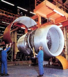
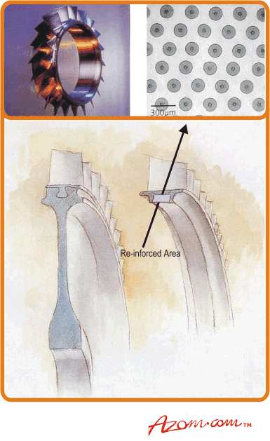
Turning finally to MMCs, the system of most relevance to aircraft engines is continuous ceramic fibre-reinforced titanium. A prime aeroengine application of MMCs will be in compressor discs and drums, in which the very high performance of the fibres can be exploited to give substantial reductions in weight (in excess of 70%) without the need to introduce the fibres into complex shapes. Savings in weight come from the elimination of the usual metal central web and hub, the hoop strength and stiffness being provided instead by a ring of reinforcing silicon carbide fibres, fig 4.
|
|
|
Figure 4. MMC bladed ring.
|
Processing Technology
Processing technology has advanced to a stage at which, with considerable care and attention, high quality components can be produced with excellent fibre registry and fatigue behaviour equivalent to typical specimen data. The risk associated with this technology is captured appropriately in the words of Petroski in his Design Paradigm: ‘The stage of greatest risk is not the leap of innovation, but some years later when daring has become routine, entrusted to less inquiring minds and executed under greater pressures of competition’. Routine process capability has yet to be determined, as indeed have the standards to be met to guarantee adequate service lives. In parallel with process developments a major effort is underway to tackle the issues of component behaviour and tolerance to defects such as fibre breakage/end distribution. This iterative process will demand further significant investment and intimate collaboration between suppliers and end users before yielding a reliable manufacturing capability, validated lifing methods, and of course component costs that are acceptable to the end user. Cost reduction is a major challenge to be met by the industry. The rate at which the considerable investment in technology development is recovered is strongly linked to the cost effectiveness of the solution. Particularly encouraging is the acute awareness of the supply industry to this critical issue. On the basis of aggressive cost reduction initiatives already in place, leading suppliers are predicting rough order of magnitude mature production costs that are within striking distance of Rolls-Royce targets of equivalence with incumbent monolithic parts.
Conclusion
Finally, a message to researchers in this field, it must be appreciated that, with the exception of the advanced versions of CMCs and MMCs, the necessary materials and processes are already in existence. Without a focused effort on the application issues concerning the materials that are available today, the industry may lose patience in advanced composites and invest in alternative technologies and design solutions.
|