FTIR spectroscopy is a robust technique for real-time in situ monitoring of a reaction or process, which can be realized in two ways: in situ through an insertion probe or via flow through cells installed in slipstreams. In the former approach, an insertion probe is introduced into the process material through a port in the vessel wall. Light guided down the probe reaches a sensor at the tip of the probe and is guided back for the analysis. The returned light is analyzed by a spectrometer fixed to the probe, where the spectrometer extracts the required analytical information. This approach is depicted in Figure 1. In the latter approach, a continuous stream of reacting liquid extracted from the vessel is piped to a spectrometer; here it is analyzed in a liquid flow cell and subsequently discarded or returned back into the process. This approach is depicted in Figure 2. Both the approaches have their own benefits and drawbacks.
Irrespective of the approach adopted, the information extracted at the end of the measurement is multifaceted and complex. Standard chemometric software can be used to analyze the spectra of complex mixtures that consist of various individual components, and then, the concentration of individual components can be calculated. Furthermore, the high specificity of IR spectroscopy allows the detection, identification, and, at times, quantification of the unfamiliar and commonly unexpected contaminants. The information acquired by this means can be used to facilitate real-time monitoring and documentation of the process reactions. After gaining the required confidence in the spectroscopic measurement, the results of the measurements can be fed back into the process control room to enable automatic pulling of the levers, opening or closing of valves, and so on.
Since there is no need to extract the sample out of the reactor or process line, the process is comfortable. The sample is analyzed as is in the vessel. In various instances, the reaction conditions are such that the processed material is at a temperature far from ambient, at a high pressure, corrosive, or any combination of these conditions. The process conditions are disrupted by the flow of processed fluid through a slipstream. In order to avoid degradation of the product during the measurement, these conditions should be maintained in the slipstream.
In contrast, slipstreams provide considerably higher flexibility. For example, if the sensing element fails during the process, withdrawing the probe and analyzing the problem would become very difficult, specifically if the vessel is pressurized. If slipstreams are used, it would be relatively easy to close the valve on the line that brings the sample to the cell, disconnect the cell from the stream, replace it, open the valve, and continue monitoring. The slipstream also facilitates a considerably wider selection of flow cells. Either ATR flow cells or transmission can be used, and virtually any sensitivity level required to optimize the signal-to-noise ratio (S/N) of the measurement can be adopted. The choice of sensing elements is limited with the use of insertion probes. For all practical uses, IR insertion probes can only use sensing elements based on the ATR spectroscopic method.
Insertion Probes
Two approaches are adopted by insertion probes to guide light toward the sensor and back. One approach is the use of fiber optics, and the other is the use of an open tube through which light is guided. Both the approaches are quite sensitive and require advanced optical designs for optimizing the performance. Moreover, both the ways lead to considerable reduction in optical signal levels and so are usually used in combination with liquid nitrogen cooled detectors. The dewars of liquid nitrogen cooled detectors have to be refilled at least every day; therefore, it is not so convenient to use them in process environments.
Figure 1 depicts a specific schematic illustration of the application of an insertion probe for the in situ analysis of process streams, particularly the Durasens DP-R Series Diamond ATR Fiberless Probe.

Figure 1. Schematic representation of the use of the Durasens DP-R Series Diamond ATR Fiberless Probe for in situ real-time stream monitoring
In this probe, fiber optics is not used to guide light between the sensor and the spectrometer. The probe is connected to the spectrometer through a flexible articulated optical arm in which only metal mirrors are used to guide light from the spectrometer to the sensing element at the end of the probe and back to the spectrometer for analysis. To eliminate atmospheric interferences from the collected spectra, the light path within the arm is enclosed in a purged environment. The arm has the ability to move up, down, and forward, and the probe can be aligned at any angle to be in line with the port configuration on the vessel or line.
This method of guiding light between a probe and a spectrometer is not affected by the spectral range restrictions usually experienced with optical fibers. The entire spectral range can be accessed. Spectral range restrictions, if any, arise from the spectrometric sensor. This method also ensures greater optical efficiency in various cases, thereby allowing the use of room temperature detectors.
As described above, ATR spectrometric sensors are used in majority of the IR probes. Yet, the application of transmission spectrometric sensors is quite common for NIR probes. The transmission sensors are not used with IR probes since shorter pathlengths are required in IR. For example, the pathlength of 100 μm is generally used in IR transmission cells. If such a shorter pathlength is used in a transmission IR probe, the process liquid enveloping the probe element would have to penetrate into this narrow space in some way from the outer side without the advantage of the fluid being forced in, as is the case in transmission flow cells.
Even if sample penetration takes place spontaneously, the liquid that penetrated between the two windows would probably become stagnant and therefore would not reflect the variations in the process, thereby making the probe ineffective. In case the space between the two windows gets obstructed in some way, the probe must be completely disassembled for cleaning and then reassembled for the next operation. A sensitive operation such as this is not practical in process environments. Hence, in spite of the attractiveness of transmission sensors, ATR remains the only feasible strategy for IR probes.
In majority of the insertion ATR probes, ATR elements that provide one or two reflections are used. These sensors offer a sensitivity that is enough for applications in which only the major components in the process stream are monitored. In some probes, multiple reflection ATR elements are used.1 Such probes offer a considerable boost up in sensitivity. In most of the instances, diamond is used as the ATR material. Diamond lattice absorptions partially conceal a part of the spectral range approximately between 1800 and 2600 cm−1 and, specifically with the multi-reflection probes, the lattice absorptions might hinder the measurements of certain compounds that have absorption bands in the affected spectral region.
Although the application of multiple reflection ATR probes might considerably step-up the sensitivity in contrast to using one or two reflection probes, even the multiple reflection probes cannot offer the huge sensitivity provided by a transmission cell with a pathlength of 200 µm.
Slipstreams
Slipstreams necessitate that the process fluid should be brought from a vessel to a cell within the spectrometer for analysis. Figure 2 is a schematic illustration of this approach. The flow of the liquid is indicated by the arrows next to the fluid lines. A stream of sample can be diverted through the flow cell and returned back with the help of a pump. In certain cases, the existing flow, or pressure, of the process fluid can be used, thereby eliminating the need for a pump. It is easy to set up the slipstream by using the same kind of access port used for insertion probes. In simple terms, additional installations are not needed for setting up the slipstream.
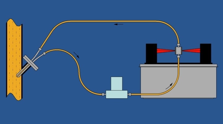
Figure 2. Schematic representation of the use of the Durasens Rapid Flow Cell attached to a slipstream via a Durasens probe-like slipstream feeder for real-time stream monitoring
The important benefit of slipstreams is that they enable the use of various distinctive types of flow cells, from single-reflection ATR cells to gas cells with a pathlength of 20 m. This allows the selection of cell pathlengths with virtually no limitation.
The pathlength of a transmission cell can be adjusted almost on demand; however, at very short pathlengths (typically less than 25 µm and usually dependent on the sample’s viscosity), the flow of liquid through the cell turns out to be hard, and accumulation of tiny particulates in the stream might lead to a clog, which will hinder the flow. The flow through the cell might become uneven, or the resistance to the flow might result in a very high backpressure in the input line. Luckily, ATR flow cells can be used for shorter pathlengths, since they can adopt single reflection or multiple reflections. The evident advantage of using ATR cells in such instances is that these cells do not restrict the flow of liquid through the cell. There is no restriction of the space above the ATR element in the cell, and it can be as large as possible to enable better flow conditions.
It should be noted that the monitoring approach depicted in Figure 2 is not limited to liquids. It can also be used for gas analysis. In the case of gas streams, gas cells are used in the place of flow cells. In general, gases are nearly a thousand times less dense than liquids, hence the pathlengths of gas cells are usually a thousand times longer. In various instances, single-pass cells with a pathlength of 10 cm are enough; however, in other cases, pathlengths of the order of tens of meters might be needed. In such cases, the cells are multiple pass cells. The beam path is folded 10 to 100 times through the cell with the help of mirrors; therefore, such cells, in spite of their huge pathlengths, can be easily fit in the same place in the spectrometer as the liquid cell does in Figure 2.
At times, the application of transmission liquid cells in slipstreams leads to the challenge of how latest is the information acquired. As shown in Figure 2, the liquid is collected from the vessel or process line and transferred to the flow cell through the slipstream. In case a shorter pathlength, of about 100 µm, is used in the cell, there could be substantial resistance to the liquid flow. In this case, the rate of flow through the slipstream gets reduced, leading to an increase in the travel time of the sample between the port and the cell. For example, if the liquid flows in a 1 m long slipstream at a speed of 5 mm/second, the travel time between the port and the flow cell is 200 seconds (or more than 3 minutes).
In such instances in which the sensitivity level needed for the measurement is such that ATR insertion probes just cannot be employed and a slipstream fed transmission cell is the only possible option, and sometimes, bypass loops are built around the cell to accelerate the flow of liquid through the slipstream by cutting short the length of the portion of slipstream input line inside which the flow rate of the sample is limited. Although this solves the initial difficulty, it can have an inadvertent result that all the flow could subsequently pass through the bypass loop. Initially, it will be difficult to regulate the split of the flow between the bypass loop and the cell but it could be complicated more by variations in the sample’s viscosity as the reaction progresses.
The Rapid Flow Cell (Durasens, Pleasantville, NY) proves to be a more effective solution since it is developed in such a way that it enables rapid unrestricted flow through the cell at any pathlength. This cell makes the best use of the siphoning effect produced by the fast flowing sample to assist in the flow of fluid through the space between the windows.
Conclusion
This article analyzed the advantages and disadvantages of the use of insertion probes over the use of slipstreams for process and reaction monitoring by using IR spectrometric approaches. Evidently, it is concluded that both the approaches have their own pros and cons. While using spectroscopic reaction or process monitoring, all the requirements imposed by the process should be carefully reviewed and all the available options should be explored. Although the insertion probes are being currently used in various applications, slipstreams2 could prove highly advantageous in specific applications.
References
1. M. Milosevic, D. Sting, and A. Rein, Diamond-Composite Sensor for ATR Spectroscopy, Spectroscopy 10(4), p. 44, (1995)
2. Paul Wilks, Process Monitoring: In-line, At-line, or Slip-Stream, Spectroscopy 21(3), p.2, (2006)
This information has been sourced, reviewed and adapted from materials provided by Durasens.
For more information on this source, please visit Durasens.