COLUMBIA can offer an extensive range of Force Balance Servo Accelerometers and Inclinometers, designed specifically to provide the user with a variety of sizes, configurations and performance levels for industrial, O.E.M. and military requirements.
Several COLUMBIA Force Balance Transducers have been in-flight missile qualified in accordance with all relevant MIL-Standards/Commercial standards and are presently being used across a range of the U.S. government’s most technically challenging military in-flight weapons systems.
COLUMBIA has also developed servo accelerometers that are TSO-Approved by the Federal Aviation Agency (F.A.A.) for flight avionics, commercial and general aircraft flight control systems.
For over three decades, dependable product performance for key applications has been one of the central features of COLUMBIA Force Balance Servo Accelerometers and Inclinometers.
The Columbia Facility
For over 50-years, self-sufficiency has been at the core of COLUMBIA’s operations: being dependent on external sources for key components, materials and services is discouraged.
COLUMBIA manufactures all the torque mechanisms used in the miniature and high performance inertial products in-house. This is done to guarantee consistent availability and precision of key components.
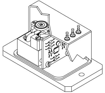
Figure 1. Force Balance Sensor. Image Credit: Columbia Research Laboratories
Manufacture of torque parts, housing and hardware for COLUMBIA Force Balance Accelerometers are carried out in COLUMBIA’s on-site shop facilities using high-speed, efficient, numerically-controlled machines.
No parts are cast in the COLUMBIA torquers. All parts are machined with careful precision and checked to stringent standards. Critical assembly operations are conducted in a “Limited Access White Room”.
COLUMBIA also hosts exceptional environmental testing capabilities “in-house”, in sine and random vibration, shock, angular and linear acceleration, and temperature.
The COLUMBIA facility and all COLUMBIA processes and procedures have been quality surveyed and are certified as fully compliant with Federal Government Quality Assurance Documents MIL-Q-9858 / MIL-I-45208.
Subtle details, such as identification engraving, label and data sheet printing, are performed on site as part of COLUMBIA’s repertoire of “in-house” capabilities.
Continued expansion of the COLUMBIA facilities and capabilities guarantees the capability to rapidly respond to customers’ economic needs for custom packaging or performance in the field of force balance accelerometers and to guarantee the highest level of product performance and accuracy available anywhere.
Technical Information
The servo force balance accelerometer can deliver exceptional performance and accuracy benefits. This fact is apparent in their widespread application use necessitating 0.1% or better overall accuracy. Unlike traditional accelerometers, the servo type incorporates a freely suspended mass subjected to an electrical equivalent mechanical spring.
Servo force balance accelerometers are available in two classes: the pendulous type, which possesses an unbalanced pivoting mass with angular displacement, and the non-pendulous type, which possesses a mass that is linearly displaced.
The behavior of all accelerometers can be explained by Newton’s second law of motion: Force equals mass multiplied by acceleration.
F = ma
This equation highlights that if a mass is to be accelerated, a proportional force must also exist. If the force can be measured, the amount of acceleration can be established.
For pendulous type accelerometers, the polar form of the equation applies: Torque equals pendulous mass multiplied by acceleration.
T = (ml) a
Where (I) stands for the distance from axes of rotation to the center of mass, and (ml) represents the pendulous mass.
Why Choose a Force Balance Sensor?
The intended use for the force balance sensor is for D.C. and low frequency acceleration measurements, such as those that occur in the motion of aircraft, vehicles and ships. These sensors have the capacity to measure levels from as low as 0.0001 g up to 200 g across a frequency range from DC to 1000 Hz.
Moreover, due to their innate sensitivity to gravity, the force balance accelerometers that have specific modifications or special features built in become superior instruments for measuring angles of inclination.
This kind of sensor, typically known as an inclinometer, is practical in applications such as platform leveling, gunsight control, pipeline leveling, borehole mapping and other low level seismic measurement applications.
Advantages
The force balance sensor is equipped with a number of advantages that result in superior performance in a range of applications, including those mentioned above.
Internal displacements within any accelerometer typically produce inaccuracies and errors in the form of excessive hysteresis, stickiness, non-linearity and non-repeatability.
LVDT, potentiometric, variable reluctance and other relative sensors tend to produce such errors because the sensing element must travel some distance in order to generate a measurable change in output.
Conversely, the output signal from a force balance accelerometer is not contingent on the displacement of an internal element being a linear function of acceleration. Internal displacements remain relatively small, usually around one ten-thousandth of an inch or less.
As well as reducing static error significantly the minute displacements that are related to the force balance sensor contribute to the fact these sensors have a relatively high natural frequency. Excessive internal displacements are not a requirement of strain gage sensors but they can suffer from instability related to effects of temperature, creep and aging.
Contrary to other low frequency accelerometers, which need a viscous media, dash pot or similar mechanical damping technique, the force balance sensor’s dynamic response can be damped and adjusted easily to a precise value by way of electronics networks.
The damping ration can be set near critical for a maximum usable response or to a higher degree or limited response and sensitivity to high frequencies. Usually, in open loop types of transducers, the damping ratio is not controlled as in the case of piezoelectric devices by way of viscous media.
In this final instance, it is not possible to control the damping ration by any tight tolerance, this is because of the viscosity changes vs. temperature. A great number of strain gage, potentiometric or LVDT type accelerometers incorporate thermostatically controlled heaters to try to stabilize damping characteristics.
Moreover, in the majority of cases the force balance accelerometer is completely self-controlled, requiring no additional signal conditioning, and has the capacity to interface directly with data acquisition systems, oscilloscopes, spectrum analyzers, digital volt meters and displays.
The full scale output is generally in the order of several volts and does not necessitate any further amplification.
How the Force Balance Sensor Works
The force balance sensor is comprised of a position detector - not one that is necessarily linear - an amplifier and an electromechanical system.
This combination has the ability to perform the function of transforming a mechanical force into a proportional current which is in turn transformed back into an equal opposing mechanical force.
The position detector monitors the position of a mass coupled to the force generator. An externally induced variance in mass position produces a combination position detector, amplifier output such as that the force generator pushes the mass back to its starting position.
The output of the sensor measures the current passing through the force generator. This current is directly proportional to the restoring force, which is equal and opposite to the input force. The input acceleration is matched by the input force via the calibrated mass (see Fig. 2).
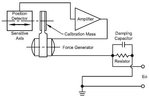
Figure 2. Black diagram of Force Balance Sensor. Image Credit: Columbia Research Laboratories
When acceleration is not present, the current passing through the force generator is reduced to zero. The force generator current can be traced with the application of a resistor in series, thereby delivering a voltage output precisely proportional to the original mechanical input.
The electronic damping is facilitated by a capacitor and positioned across the sampling resistor.
The capacitor and sampling resistor include a lead network which produces a reduction at high frequencies of the amplifier voltage needed to drive the restoring current Fig. 3 shows the relationship between frequency response and damping ratio as applied to a conventional force balance accelerometer.
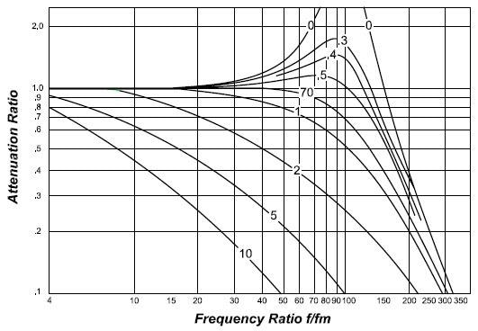
Figure 3. Frequency Response. Image Credit: Columbia Research Laboratories
The Columbia “H.P.” (High Performance Torquer)
A force balance accelerometer requires a suspended mass in order to translate acceleration into a measurable force. A means must also be present to apply a current through a coil in a magnetic circuit in order to balance out the force caused by the applied acceleration.
This assembly is referred to in force balance circles as a forcer or torquer.
A key, fundamental requirement of a torquer is the method employed to optimally support the mass. Preferably, the means of support should enable movement of the mass in only a single, well-established direction and, at the same time, eradicate motion in remaining across axis directions.
Furthermore, the support should not introduce any forces of its own, such as friction or spring effects. The mass support should be robust enough to endure the required physical environments without deteriorating.
Three frequently used methods that accelerometer manufacturers incorporate include: flexures, taut bands and bearings. The flexure and taut band systems both come with similar pros and cons. They are effectively frictionless and, as a result, produce exceptional repeatability results.
The flexure has an outstanding, sensitive axis definition, while the taut band requires support due to sagging under cross axis loading in fluid in order to limit its sensitivity to cross loads and vibration.
Both are prone to damage from shock. Metal flexures may experience permanent deformation, leading to zero bias errors, while fragile non-metallic flexures fracture may catastrophically fail in the same circumstances.
Stiff flexures also generate non-linear output characteristics as a result of their inherent self-restoring tendency. This non-linearity is not evident in bearing type accelerometers.
COLUMBIA accelerometers incorporate bearings to support a pendulous mass. The most cost-effective COLUMBIA accelerometers use a pivot and jewel bearing. This system is appropriate for applications where cost is a key factor and environmental requirements and precision are flexible.
The more advanced COLUMBIA accelerometers utilize high performance ball bearings suspension in lieu of the pivot and jewel. The physical tolerances of these bearings are more than 20x tighter than those of a conventional pivot and jewel bearing.
Their performance is up there with the best flexures, while at the same time, they have the capacity to survive severe shock and vibration environments.
Other advantages the COLUMBIA “H.P.” TORQUER offers include no pivot-flop, low rectification, no progressive deterioration and exceptional static performance under vibration.
All stock and “H.P.” torquers are manufactured on-site at COLUMBIA to ensure consistent “unit to unit” reliability and performance.
Explanation of Characteristics
This section refers to a number of specifications that can help support the evaluation and selection of force balance sensors for specific applications.
Scale Factor
Scale Factor is the change in ratio in output to a change in the intended input for measuring or application. The scale factor calibration that is standard in COLUMBIA accelerometers is expressed as volts/g or volts/radian/sec2. The scale factor of the inclinometer is also expressed as volts/g. However, it must be paired with the following equation,
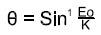
In order to determine the angle measured; Eo being the measured output, and K emphasizing the output at 90° or one g (See Fig. 4). It is not necessary to convert when the inclinometer is paired with a COLUMBIA DVM calibrated to read directly in degrees.
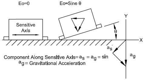
Figure 4. Scale Factor. Image Credit: Columbia Research Laboratories
Bias
Bias is the measured sensor output when there is no application of mechanical input.
Input Axis
An input axis is an axis along which a maximum output is caused by an acceleration or inclination of the case.
Cross Axis Sensitivity
Cross axis sensitivity refers to the constant that proportionally relates a variation of accelerometer or inclinometer output to cross acceleration or inclination.
Composite Error
Composite error refers to the maximum deviation of the output data from the output function as specified. Composite error may incorporate the effects of hysteresis, resolution, non-repeatability, non-linearity and other unknowns in the output data. It is typically expressed as a percentage of the output range.
Repeatability
Repeatability is a sensor’s ability to reproduce a given output of performance characteristics under duplicate input and environmental conditions. Repeatability is comprised of the effects of threshold, resolution and uncertainties across other performance characteristics.
Non-Linearity
Non-Linearity is a reference to the deviation of the output data from the straight line determined by the zero input bias and scale factor coefficient (see Fig. 5, Non-linearity).
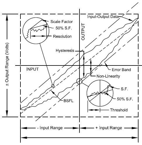
Figure 5. Input-Output Characteristics of a typical Force-Balance Accelerometer. Image Credit: Columbia Research Laboratories
Hysteresis Error
Hysteresis error refers to the difference between output signals for increasing and decreasing inputs at that input for which the maximum difference is measured post-cycling through the input scan (see Fig. 5, Hysteresis).
Resolution
Resolution is the greatest value of the minimum change in input for inputs more than the threshold, which generates a change in output equal to some particular percentage (at least fifty percent) of the change in output expected utilizing the nominal scale factor (see to Fig. 5, Resolution).
Threshold
Threshold is the greatest absolute value of the minimum input that generates an output equal to a specific percentage (at least fifty percent) of the expected output utilizing the nominal scale factor (see Fig. 5, threshold).
Rectification Error
Rectification error is a steady-state error in the output arising from vibratory disturbances that act on an accelerometer or inclinometer.

This information has been sourced, reviewed and adapted from materials provided by Columbia Research Laboratories, Inc.
For more information on this source, please visit Columbia Research Laboratories, Inc.