The Zurich Instruments VHFLI Lock-in Amplifier is a versatile digital measurement device operating over a frequency range from DC to 50 MHz (extendable to 200 MHz with the VHF-F200M option).
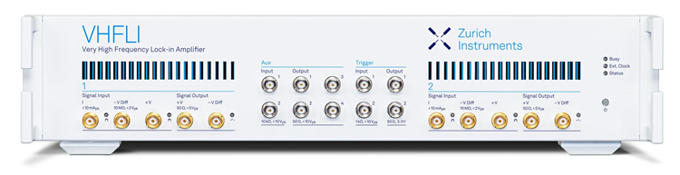
Image Credit: Zurich Instruments
Covering applications in optics and photonics, sensor and electronic device development, nanotechnology, scanning probe microscopy, surface and materials science, the VHFLI Lock-in Amplifier delivers high-performance signal analysis and control.
Engineered for leading analog performance, it includes the established capabilities of previous instrument generations that introduced integrated feedback loops, multi-frequency operation, arbitrary waveform generation, and sideband analysis.
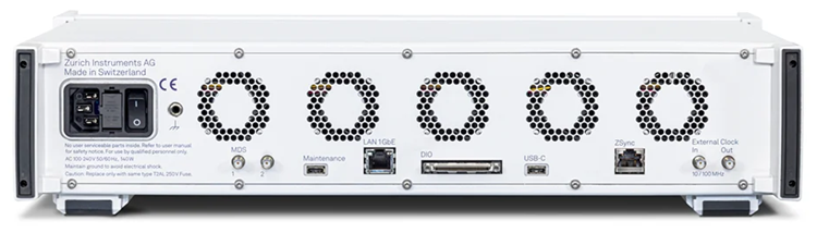
Image Credit: Zurich Instruments
With the VHFLI Lock-in Amplifier, users can:
- Coordinate measurement sequences by synchronizing pulses, triggers, measurements, and controllers using the LabOne Timeline Module
- Analyze signals from multiple viewpoints by operating the Scope, Sweeper, Spectrum Analyzer, and more simultaneously
- Configure accurate multichannel current and voltage measurements rapidly, supported by an ultra-low noise floor
- Operate efficiently using the LabOne GUI and APIs, designed for intuitive use and laboratory-ready workflows
- Record rapid signal variations with short time constants while improving data throughput
- Execute mathematical operations on signals using the Arithmetic Unit
- Access industry-leading performance at a competitive price
- Enhance signal quality through differential inputs
VHFLI Lock-in Amplifier
Video Credit: Zurich Instruments
Key Features
- Analyze, generate, and control signals from DC up to 50 MHz (extendable to 200 MHz with the VHF-F200M option)
- Manage complex CW and pulsed measurement sequences using the LabOne® Timeline Module
- LabOne® toolset includes Scope, Sweeper, and Spectrum Analyzer
- Accurately measure up to two current and voltage channels
- Short measurement times combined with a low noise floor
- Extend functionality with available upgrade options
Powered by LabOne®
The VHFLI Lock-in Amplifier is equipped with LabOne® control software, which simplifies setup through an intuitive graphical user interface. It also enables comprehensive control of the full measurement toolset, including the lock-ins, a dual-channel oscilloscope with FFT, a parametric sweeper, a spectrum analyzer, and additional features.
Furthermore, all functions and data acquisition are accessible through major programming languages to support seamless integration: LabVIEW™, MATLAB®, C, .NET, and Python are supported.
LabOne Overview
Video Credit: Zurich Instruments
Applications
The VHFLI Lock-in Amplifier features low input noise, a broad analysis bandwidth, and a short low-pass filter time constant, making it well suited for demanding signal analysis applications.
- Optics and photonics: Raman spectroscopy, pump-probe spectroscopy, nano-optomechanics, optical PLL, THz spectroscopy
- Materials science: Carrier mobility, carrier density, Hall effect
- Failure analysis: Laser voltage probing and imaging
- Scanning probe microscopy: AFM, STM, MFM
- Sensors: MEMS, NEMS, quantum sensing
Specifications
Source: Zurich Instruments
| General |
|
| Dimensions |
32.5 × 44.5 × 10 cm (with handle); 19‑inch rack compatible |
| Weight |
6.3 kg (14 lb) |
| Power supply AC line |
100-240 V, 50/60 Hz |
| PC operating systems |
See LabOne Compatibility |
| Signal inputs |
|
| Number of Lock-in Units |
2 |
| Channel Type |
1 Voltage (Differential and single ended) and 1 Current per Lock-in Unit |
| Frequency range |
DC - 50 MHz, DC - 200 MHz with VHF-F200M option |
| Input impedance |
50 Ω, 10 MΩ, selectable |
| Input voltage noise |
< 3 nV/√Hz (> 50 kHz) |
| Input current noise |
~ 50 fA/sqrt(Hz) @1 kHz |
| Voltage Input ranges |
±5 mV to ±2 V |
| Current Input Ranges |
±10 nA to ±10 mA |
| Current Input Max Bandwidth |
50 MHz (3dB, for 10, 1 and 0.1 mA range) |
| Input AC coupling cutoff frequency |
~300 kHz (50 Ω) |
| A/D conversion |
14 bits, 2 GSa/s |
| Connectors |
BNC |
| Signal outputs |
|
| Number of output channels |
2 |
| Output type |
Voltage, Differential and single ended |
| Frequency range |
30 MHz (0.1 dB), > 200 MHz (3 dB) |
| Output ranges |
±5 mV, ±50 mV, ±500 mV, ±5 V |
| Signal output impedance |
50 Ω |
| Signal adder |
Auxiliary input (digital adder) |
| Voltage output noise floor |
40 nV/√Hz (5V range), 4 nV/√Hz (5 mV range) |
| D/A conversion |
14 bit, 2 GSa/s |
| Connectors |
BNC |
| Reference and triggers |
|
| Triggers |
2 inputs, 2 outputs |
| Frequency resolution |
7.1 µHz |
| Phase angle resolution |
2.7 µº |
| Trigger Connectors |
BNC front panel |
| Trigger inputs impedance |
low: 50 Ω, high: 1 kΩ |
| Trigger inputs levels |
low impedance: ±5 V, high: ±10 V |
| Trigger outputs impedance |
50 Ω, 1 kΩ |
| Trigger outputs levels |
3.3 V TTL |
| Demodulators |
|
| Frequency range |
DC - 50 MHz, DC - 200 MHz with VHF-F200M option |
| Number of demodulators |
2 dual-phase (8 with VHF-MD option) |
| Number of oscillators |
2 (8 with VHF-MD option) |
| Output sample rate on LAN/USB 3.0 |
2 MSa/s maximum (total all demodulators)
25 MSa/s triggered mode |
| Output sample rate on Aux outputs |
25 MSa/s, 14 bit |
| Dynamic reserve |
120 dB typical |
| Filter time constant |
14 ns to 21 s |
| Filter bandwidth |
3.2 mHz to 11 MHz |
| Filter slope |
6, 12, 18, 24 dB/Oct |
| Scope |
|
| Input channels |
Signal inputs |
| Scope modes |
Time domain, frequency domain (FFT) |
| Number of display channels |
2 |
| Trigger mode |
Edge |
| Vertical resolution |
14 bits |
| Cursor math |
Location, area, wave, peak, tracking, histogram |
| Sweeper |
|
| Scan parameters |
Oscillator frequency, demodulator phase shift, auxiliary offset, signal output amplitudes, signal output offset |
| Parameter sweep ranges |
Full range, linear and logarithmic |
| Parameter sweep resolution |
Arbitrary, defined by start/stop value, and number of sweep points |
| Display parameters |
Demodulator output (X, Y, R, Θ, f) |
| Display options |
Single plot, dual plot (e.g. Bode plot), multi-trace |
| Statistical options |
Amplitude, spectral density, power |
| Spectrum Analyzer |
|
| Centre frequency range |
0-50 MHz (200 MHz w/ F200M option) |
| Spectrum modes |
FFT(X+iY), FFT(R), FFT(θ), FFT((dθ/dt)/2π) |
| Statistical options |
Amplitude, spectral density, power |
| Averaging modes |
None, exponential moving average |
| Max number of samples per spectrum |
8.4 MSa |
| Max span |
1.56 MHz |
| Window functions |
Rectangular, Hann, Hamming, Blackman Harris, Flat Top, Exponential, cosine, cosine squared |
| Auxiliary ports |
|
| Auxiliary inputs |
2 channels, ± 10 V, > 150 MHz BW
Digital adder with voltage input |
| Auxiliary outputs |
4 channels, ± 10 V > 30 MHz BW |
| Auxiliary output impedance |
50 Ω |
| Auxiliary ports amplitude |
± 10 V, ±1 V, ±100 mV (in and out) |
| Auxiliary output resolution |
0.012 mV |
| Auxiliary outputs signals |
R, Θ, X, Y, manual, options |
| Connectors |
BNC |
| Connectivity and others |
|
| Host connection |
LAN / Ethernet, 1 Gbit/s
USB 3.0 |
| Digital I/O |
32 bits, 50 MHz |
| Clock |
10 MHz or 100 MHz input and output |
VHFLI Available Options
VHF-F200M
Frequency Extension
Key Features
- Extends the VHFLI instrument’s frequency range from 50 to 200 MHz
- Compatible with additional options
- Field-upgradable option
VHF-MD
Multi-Demodulator Option
Key Features
- Enables arbitrary frequency selection across all eight demodulators
- Includes an output adder to combine up to eight sinusoidal signals
- Adds six additional demodulators and oscillators
- Free oscillator selection for all demodulators
VHF-MOD
Modulation Analysis Option
Key Features
-
- Includes two independent AM/FM modulation units, each with three frequency components
- Provides adjustable filter parameters for every frequency component
- Supports concurrent sideband modulation and demodulation
- Features a dual-modulator (signal output) configuration
- Sideband separation (single-sided modulation)
- Harmonic sideband analysis (2 sidebands)
VHF-PID
Quad PID/PLL Controller Option
Key Features
- Output options include signal amplitudes, oscillator frequencies, and demodulator phase
- Input options support demodulator data, including X, Y, amplitude, and phase
- Provides phase unwrapping for demodulator phase data (±1024 π)
- Includes four independent PID controllers
- Low-pass filter for the derivative branch
VHF-AWG
Arbitrary Waveform Generator
Key Features
- Integration with the Timeline Module
- 200 MHz bandwidth, 2 GSa/s
- 14-bit vertical resolution
- Dual 200 MHz AWG