Due to their high current and power densities, advanced battery systems require the use of high-performance safety components.
The GigaFuse from GIGAVAC, a Sensata Technologies trademark, is a fast-acting electromechanical device with low heat production that allows circuit trips at certain currents.
It is available in both passive and passive/active configurations, and its design makes it easy to connect with contactors while eliminating the thermal aging fatigue that is prevalent with DC fuses.
Highlights
- Extensive automotive understanding, including supply chain and quality
- Provide engineering, commercial support, and a global/local strategy
- Global production capacity ensures supply
- Leading provider of automobile components
Features
- Functional Safety: Passive technologies use electromechanical release mechanisms to ensure functional safety.
- Quick disconnect: Clears in less than 3 ms, regardless of current level
- Coordination of system protection: The adjustable trip current enables easy coupling with high-voltage contactors.
- Optional active control allows designers to choose between active and passive protection solutions.
- Interrupt capability of up to 10 MW
- 400 A continuous current carry (4/0 busbars); consult engineering for greater currents
Applications

Image Credit: Sensata Technologies, Inc.
The dimensions are in millimetres or inches. Unless otherwise specified, all dimensions have a tolerance of +/-1 mm.
The dimensions and tolerances indicated are from the product envelope drawing; when developing for specific applications, please contact Sensata to verify the values.
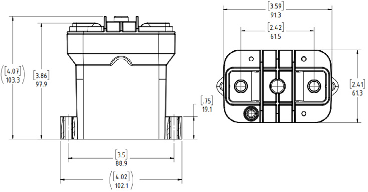
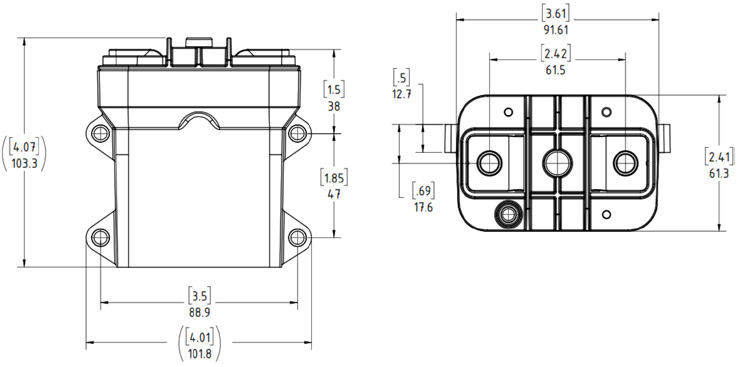
Image Credit: Sensata Technologies, Inc.
Mounting
- Use M5 or No. 10 screws
- Torque range: 1.7–4 Nm (15–35 in-lb).
Case Material
- Thermoplastic Polyamide Resin
Power Connection
- M8 x 1.25 Female
- Torque: 12–18 Nm [106–159 in-lb]
Pyro Connection
- See TE Instruction Sheet 411-78033 for additional connector information.
- Qualified for LV 16 and USCAR
- Initiator resistance: ≥ 1.7 Ω to ≤ 2.5 Ω
- Triggering pulse current ranges from 1.75 A/0.5 ms to 1.2 A/2.0 ms
- Diagnostic current: ≤ 100 mA
- No Trigger Current: ≤ 0.4 A or ≤ 5.0 A / 4 μs
- Color of connection retainer may change based on supplier availability
Specifications
Source: Sensata Technologies, Inc.
| Specifications |
Units |
Data |
| Rated Voltage |
V |
1000 |
| Continuous Current Rating 2 |
A |
400 |
| Maximum Breaking Power 3 |
MW |
10 |
| Fault Clear Time at 10 MW 4 |
ms |
3 |
| Device Resistance, beginning of life |
mΩ |
< 0.15 |
| Trip Tolerance |
A |
+100/-400 |
| Insulation Resistance After Interrupt (1000 VDC) 4 |
MΩ |
≥ 0.5 |
| Operating Temperature (Ambient) 5 |
°C |
-40 to +85 |
| Allowed Terminal Temperature Maximum 6 |
°C |
150 |
| Trip Sensitivity to Mechanical Shock 7 |
50 G powered
100 G unpowered |
| Vibration 8 |
5 G RMS Sinusoidal, 12 hr/axis,
10-2000 Hz, 400 A continuous |
| Mass |
g |
750, Passive, 790, Active |
General Notes
- For customers who can use a vented device, contact Sensata Technologies for further details.
- The current rating (continuous and momentary) is determined by bus bar size and customer-specific circumstances. For specific details, contact Sensata Technologies.
- Application performance may vary depending on client environment and system isolation needs. Validated for 650 V, 15.5 kA, and 12 μH system inductance. Up to 850 V, 12 kA, and 4 μH system inductance. Contact Sensata Engineering if a 1000 V application requires more than 3 kA.
- Clear time below 5 kA can be up to 4 ms maximum. IR after 8 MW interrupt > 1 MΩ.
- Insulation resistance (IR) depends on the power level of the maximum interrupt load and rises with lower power levels or system inductance. When the system inductance exceeds 4 uH, the IR after a solitary short circuit may be less than 0.5 M. When measured at the system level, performance will improve after an interrupt.
- The device may function at higher ambient temperatures with reduced current carry while remaining below maximum terminal temperature.
- Measured from the top of the bus bar at the fastened junction. The customer is responsible for ensuring that this requirement is satisfied; otherwise, equipment may be harmed.
- Sensata Technologies suggests aligning the Z axis orthogonal to mechanical shock pulses for reliable performance under load. Sensitivity depends on the trip setting; for additional information, contact Sensata Technologies. The picture depicts the axis orientation.
- Performance varies on vibration profile and trip level; consult Sensata Technologies for unique needs.
- For automotive applications, please schedule a technical session with Sensata Technologies Application Engineering.
Momentary Current Curve
Rise in terminal temperature at 80 °C along a specified curve.
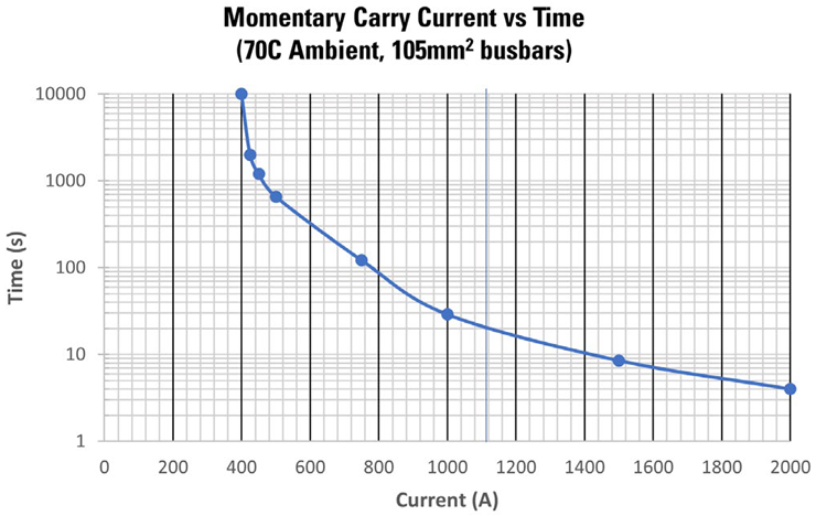
Image Credit: Sensata Technologies, Inc.
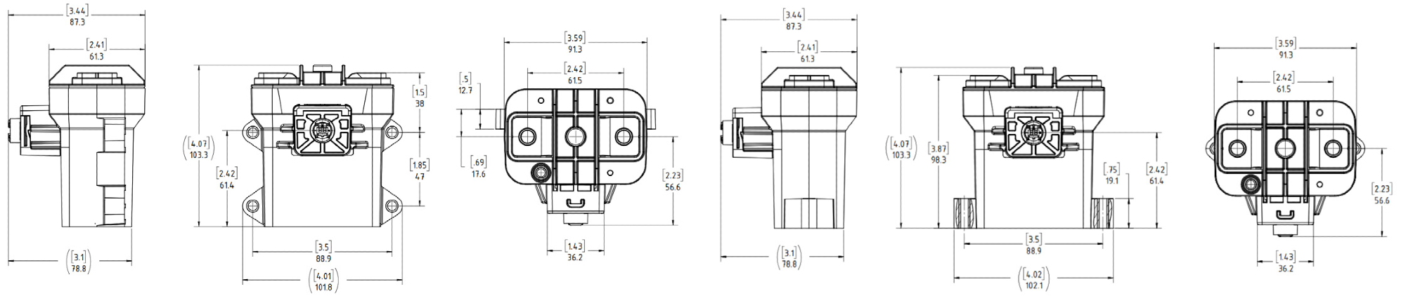
Image Credit: Sensata Technologies, Inc.