The GIGAVAC GV21 Series contactors are hermetically sealed, gas-filled units designed for use in harsh environments. The compact GV21 Series features contact voltage ratings ranging from 12 VDC to 900 VDC and a hot switchable continuous carry current of 100 A, making it ideal for handling challenging applications.
GIGAVAC's unique switching systems can be installed in any location and are sealed to withstand harsh environments. The GV21 Series contactors are RoHS, CE, and IATF-16949 compliant and designed to meet these requirements.
Features
- The product is hermetically sealed and 100 % safe. It does not depend on the mounting location.
- Provides high voltage isolation between open contacts and an inert gas-filled chamber
- An inert gas-filled contact chamber provides high voltage isolation between open contacts.
- Performs in hazardous settings without polluting contacts
- Suitable for use in hazardous or classified working conditions
- Designed and constructed in line with IATF-16949
- Using flying leads for coil connections
Applications
- Photovoltaic controls
- Energy Storage Systems
- Battery-powered electric automobiles
- Protection for DC motor controllers
- DC fast charging
Specifications
Source: Sensata Technologies, Inc.
| . |
. |
. |
| Contact Arrangement |
|
Main Contacts SPST-NO (Form X) |
| Mechanical Life |
|
One million cycles |
| Contact Resistance |
|
0.5 mΩ (max) @ 100 A |
| Shock, 11 ms 1/2 sine (operating) |
|
20G peak |
| Sine Vibration, 55–2000 Hz. |
|
20G peak |
| Weight |
|
6.7 oz (190 g) |
| Voltage Rating: Main Contacts (max) |
|
900 VDC |
Current Rating:
Main Contacts |
Continuous (8.4 mm2 / 8 AWG)1 |
100 A |
| Continuous (21 mm2 / 4 AWG)1 |
150 A |
| Short Term -- 3 Minutes2 |
200 A |
Maximum Short Circuit Current
(1/2 cycle, 60 Hz) (through closed contacts) |
1250 A |
| Dielectric Withstand Voltage (ASTM D149) |
Between Open Contacts |
> 5000 Vrms |
| Contacts to Coil |
> 3000 Vrms |
Insulation Resistance, Terminal to
Terminal/Terminals to Coil |
When New |
500 MΩ, min. @ 500 Vdc |
| At End of Life |
50 MΩ, min. @ 500 Vdc |
| Operating Temperature Range |
|
-40 °C to 85 °C |
| Environmental Seal |
|
Exceeds IP67 and IP69 |
| Salt Fog Spray |
|
MIL-STD-810G |
1. Current rating depends on conductor size. Keep power terminals below 150 °C (maximum).
2. Three minutes at +40 °C ambient with 8.4 mm2 (#8 AWG) conductor
Coil Ratings at 25 °C
Source: Sensata Technologies, Inc.
| . |
. |
. |
. |
| Nominal Voltage |
12 VDC |
24 VDC |
48 VDC |
| Maximum Voltage |
16 VDC |
28 VDC |
52 VDC |
| Pick Up Voltage |
Up to 9.6 VDC |
16 VDC |
33 VDC |
| Drop Out Voltage |
1.2 VDC |
2.4 VDC |
4.8 VDC |
| Coil Current |
461 mA |
250 mA |
122 mA |
| Coil Power |
5.5 W |
6.0 W |
6.0 W |
| Coil Resistance ± 5 % (ohms) |
26 |
96 |
392 |
| Operate Time |
25 ms |
| Release Time |
10 ms |
DC Power Switching Cycles
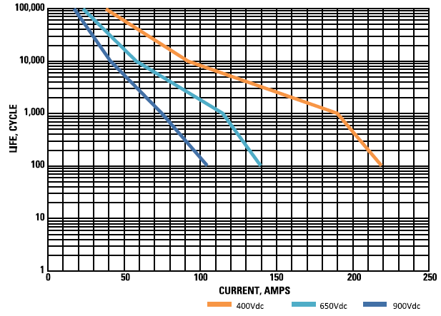
Image Credit: Sensata Technologies, Inc.
Dimensions
- Dimensions are expressed in millimeters
- The coil terminals are X1 (+) and X2 (-)
- Unless specified, all measures are +/- 0.5 mm

Image Credit: Sensata Technologies, Inc.
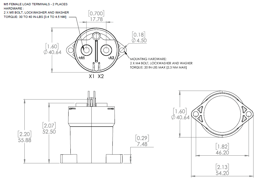
Image Credit: Sensata Technologies, Inc.