The RoadScan™ 30 system from Geophysical Survey Systems Inc. (GSSI) offers an effective tool for rapidly determining pavement layers at high speeds. It can collect data densities that cannot be obtained using other labor-intensive methods often used for pavement testing.

Image Credit: Geophysical Survey Systems
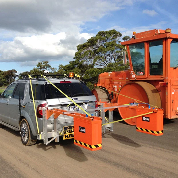
Image Credit: Geophysical Survey Systems
Applications
- Assess base and sub-base conditions
- NDT road evaluation
- Measure asphalt before milling operations
- Measure pavement thickness
- Determine areas to core
Features
- SIR 30 control unit
- SIR 30 transit case
- SIR 30 power supply
- 1 or 2 GHz Horn antenna
- 7-m Control cable
- Wheel-mounted distance measuring instrument (DMI)
- Two-year warranty
Quick and Effective Road Analysis Surveys
Users can determine pavement layer thickness and evaluate base and sub-base layers with limited, to no need, for coring.

Image Credit: Geophysical Survey Systems
Non-Destructive Pavement Testing
The RoadScan can rapidly collect pavement layer thickness data. The system obtains data at highway speeds, which avoids the need for lane closures and offers a safer working environment.
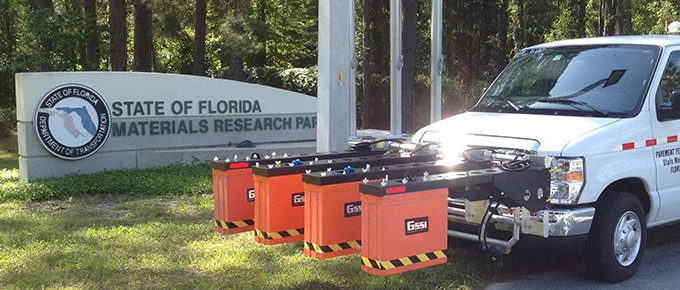
Image Credit: Geophysical Survey Systems
Deliver Pavement Evaluation Results
Users can easily export data as ASCII output files for simple data transfer to other software programs. Alternatively, data results can be migrated as Google Earth™ .kml file for optimized visualization.

Image Credit: Geophysical Survey Systems
Data Examples
Pavement Layer Data 1
Data demonstrates the base layer (green) with original pavement (red) and pavement overlay (blue). This data was gathered with the help of the RoadScan 30 featuring the 1 GHz Horn antenna.
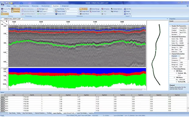
Image Credit: Geophysical Survey Systems
Pavement Layer Data 2
Dual-channel data represents data related to pavement layer (top profile) gathered using a 2-GHz Horn antenna, as well as base/sub-base layer data gathered using a 400-MHz antenna (bottom profile).
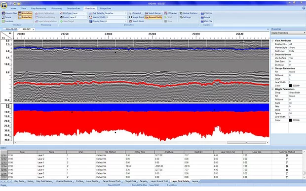
Image Credit: Geophysical Survey Systems
Pavement Layer Data Exported to Google Earth™
Users can deliver outcomes with ASCII output files for simple data transfer to other software programs. This data example constitutes RoadScan 30 data outcomes combined with Google Earth™.
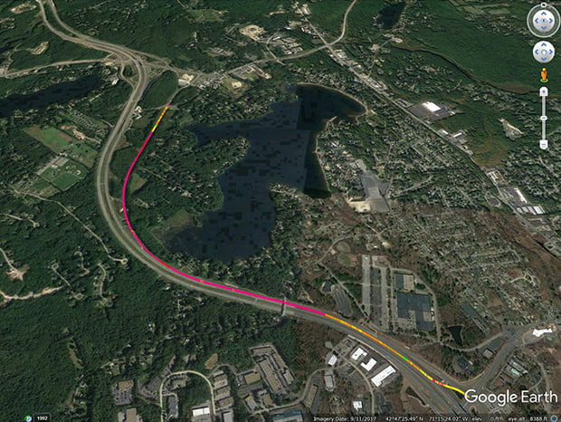
Image Credit: Geophysical Survey Systems
Specifications
Source: Geophysical Survey Systems
| System |
SIR 30 |
| Antenna support |
Compatible with all GSSI analog antennas |
| Number of channels |
Records data from 1 to 4 hardware channels simultaneously; two 4 channel systems can be connected to form an 8 channel system |
| Data storage |
Internal memory: 900 GB, GPS data logged internally |
| Display modes |
Linescan and O-scope. In Linescan display, 256 color bins are used to represent the amplitude and polarity of the signal |
| Operational modes |
External laptop, standalone with external monitor and keyboard or remote command set |
| Data acquisition |
| Data format |
RADAN® (.dzt) |
| Scan rate interval |
User-Selectable |
| Output data resolution |
32-bit |
| 1-4 Channels @ 100 KHZ PRF |
Samples | Max Rate (scans/Sec) |
| |
256 | 326 / 512 | 178 / 1024 | 93 / 2048 | 48 / 4096 | 24 / 8192 | 12 / 16,384 | 8 |
| 1-4 Channels @ 800 KHZ PRF |
Samples | Max Rate (scans/Sec) |
| |
256 | 1449 / 512 | 990 / 1024 | 606 / 2048 | 341 / 4096 | 182 / 8192 | 94 / 16,384 | 48 |
| Samples per scan |
256, 512, 1024, 2048, 4096, 8192, 16,384 |
| Time range |
0-20,000 nanoseconds full scale, user-selectable Gain: Manual adjustment from -42 to +126 dB. Number of segments in gain curve is user-selectable from 1 to 8. |
| Standard real-time filters |
Linescan and O-scope. Infinite Impulse Response (IIR) - Low and High Pass, vertical and horizontal Finite Impulse Response (FIR) - Low and High Pass, vertical and horizontal |
| Advanced real-time filters |
Migration, Surface Position Tracking, Signal Floor Tracking, Adaptive Background Removal |
| External marker |
Three different inputs/codes: Antenna, Front panel, Accessory connector |
| Automatic system setups |
Linescan and O-scope. Storage of an unlimited number of system setup files for different survey conditions and/or antenna deployment configurations |
| Languages |
|
| English and Chinese |
| Operating |
|
| Operating temperature |
-10 °C to 50 °C external (14 °F to 122 °F) |
| Power |
260 W max at 95-250 VAC 50/60 Hz with the AC supply or 30 A max continuous at +10 VDC to +28 VDC |
| Transmit rate |
Up to 800 KHz (International), US/Canada and CE rates depend on antenna model |
| Input/Output |
| Available ports |
Antenna inputs (2 or 4), Survey wheel, Marker, DC power input, Serial RS232 (GPS port), Sync connector, Accessory connector, HDMI video, Ethernet to PC, 4 USB ports |
| Mechanical |
| Dimensions |
17.7 x 13 x 5.1 in (45 x 33 x 13 cm) |
| Weight |
18.5 lbs (8.4 kg) |
| Relative humidity |
<95% non-condensing |
| Storage temperature |
-40 °C to 60 °C |
Accessories
Antenna Vehicle Front Mount
This RoadScan system accessory has been engineered for semi-permanent installation on a vehicle. In the case of in-use operation, a mounting bracket should be welded to the vehicle frame.

Image Credit: Geophysical Survey Systems
Antenna Vehicle Trailer Mount
This RoadScan system accessory is an attachable/removable option for users who choose to use the vehicle trailer hitch. This accessory can be easily disintegrated for storage and transportation.
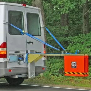
Image Credit: Geophysical Survey Systems