Powered by Nexus™, Flex NX® is the most potent and effective concrete scanner available. With an integrated touchscreen display, this all-in-one scanner offers effortless operation.
Data collection modes use the simultaneous standard and cross-polarized antenna technique. Its Flex Mode enables rapid prospecting without the need for grids, while Flex Grid enables structured, grid-based scanning for streamlined post-processing workflows and precise real-time mark outs. Flex NX also allows users to view the data on a connected tablet or phone.
Flex NX can be used on its own or connected to an NX15 or NX25 wireless antenna for a flexible configuration that resolves issues associated with concrete scanning. After configuration, results can be easily uploaded to GSSI Fusion to generate informative and professional reports quickly.
Key Features
- Display: 17.8 cm (7 in), High Resolution Touchscreen
- Depth Range: Flex NX and NX25: 0-75 cm (0-30 in), NX15: 0-150 cm (0-60 in) based on site conditions
- Environmental: IP65, -20 °C to +50 °C (-4 °F to +122 °F)
- Product Support: Comprehensive training, two-year warranty
Concrete Scanning Made Easy
Wireless Made Easy
Flex NX® enables seamless coupling of wireless NX satellite antennas using Tap-to-Connect technology, as well as wireless data transmission and software upgrades.
Get the Full Picture
Flex NX provides a comprehensive view by delivering a one-pass cross-polarization design that enables users to swiftly detect and identify targets.
Make the Complex Simple
Flex NX's revolutionary Flex Positioning technology allows users to instantly pinpoint regions of interest in real time, without the need for grids.
Deliver Results
Findings can accurately be marked on the ground for seamless creation and sharing of interactive reports before leaving the jobsite.
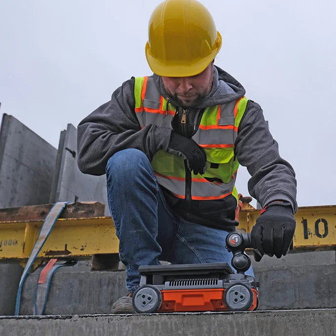
Image Credit: Geophysical Survey Systems
Don't Settle for Incomplete Solutions
Tackle Any Job
Flex NX and NX wireless antennas’ flexible design allows users to manage any complexities arising at the jobsite.
The Versatility Users Need
Results can be viewed directly in Flex NX or quickly connected to a tablet or phone for various display options when needed.
Choose Setup
The Flex NX and NX antennas have a universal mount design that helps reduce fatigue and improve comfort. This allows for switching between the extension pole, handle, or off-the-shelf mounting accessories.
Complex Problems, Many Solutions
Data collection and viewing are made simple due to various data collection and visualization modes offered by Flex NX, such as one-pass cross pol, LineScan, and the new Flex Mode. This enables users to deliver trusted results flexibly.
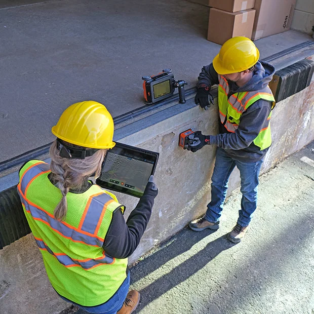
Image Credit: Geophysical Survey Systems
Users’ Trusted Partner
The Flex NX system is built to keep working reliably in harsh environmental conditions, including very hot or cold temperatures, dusty environments, and exposure to water.
Jobsite Proven
- Rated IP65
- High-capacity Lithium-ion batteries
- -20 °C to +50 °C (-4 °F to +122 °F)
Geophysical Survey Systems' Promise
In addition to the two-year equipment warranty, Geophysical Survey Systems (GSS) also provides expertise, unparalleled customer support, and extensive training.

Image Credit: Geophysical Survey Systems
Data Examples
One-Pass Cross Pol
Without viewing both standard and cross-polarized data together, users only get part of the image. Flex NX’s dual-channel feature helps identify targets that may not be visible with a single channel.
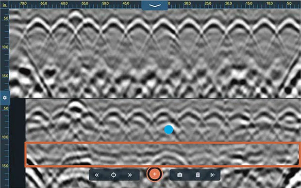
This example shows a suspended slab with a top rebar layer above a hard-to-see PVC electrical conduit. Data from the standard antenna (top) shows a series of high-amplitude rebar targets obscuring the PVC conduit (blue dot). The cross pol data (bottom) shows the hidden PVC conduit and the clearly defined bottom of the slab interface (orange box). Also visible are the structural elements supporting the slab. Image Credit: Geophysical Survey Systems
Multiple Display Options
Depending on the need, users can easily switch between single-channel and dual-channel display modes. The easy-to-use target-tagging design helps accurately place the labeled targets.
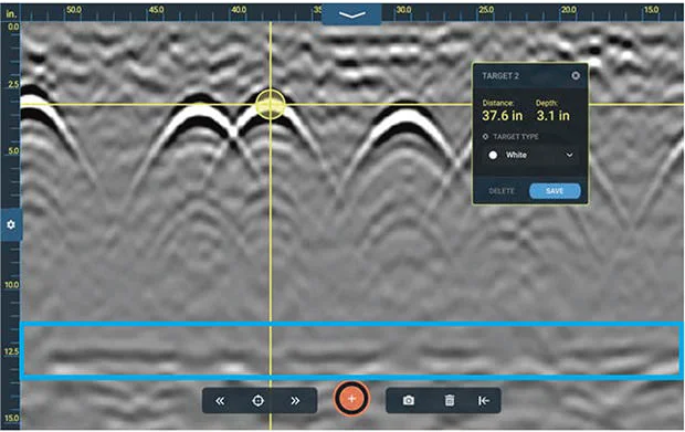
This example was collected with Flex NX on the concrete foundation of a large commercial building. Additionally, this data shows a layer of large rebar within the foundation. The concrete-air interface is the long flat reflector (blue box) at the bottom of the data file. Image Credit: Geophysical Survey Systems
NX15: See Deeper Targets
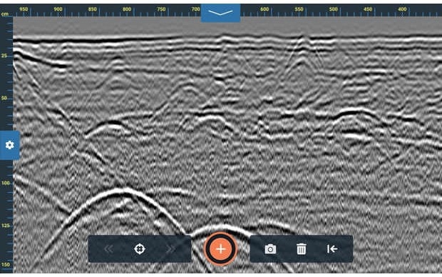
Deeply buried targets below non-reinforced concrete. This profile highlights NX15’s ideal combination of resolution and depth penetration. Note the excellent detail at the slab/grade contact, and the highly visible utility targets at the bottom of the profile. Image Credit: Geophysical Survey Systems
NX15: Clearly Resolve Near Surface Targets
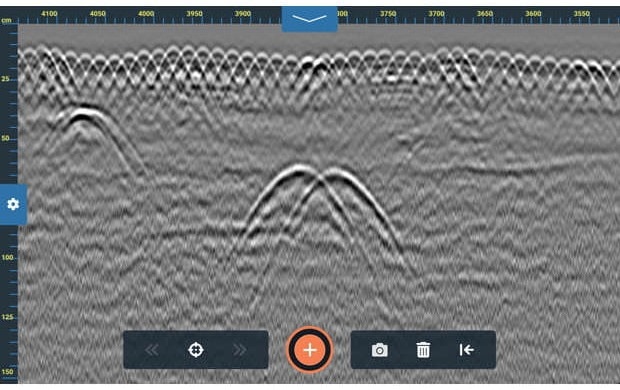
This data was collected with the NX15 accessory antenna and shows numerous targets beneath a reinforced concrete slab. Each strand of the shallow wire-mesh reinforcement is visible, and closely spaced subgrade targets are clearly defined. Image Credit: Geophysical Survey Systems
Flex Mode Imaging
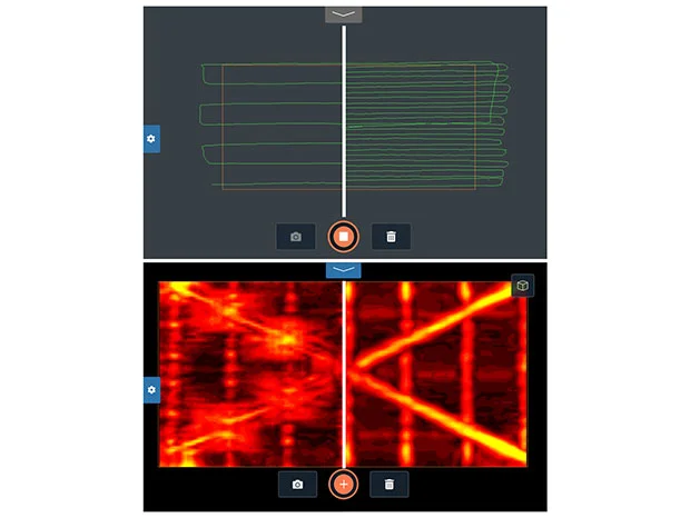
Image Credit: Geophysical Survey Systems
The Powered by Nexus™ platform provides multiple opportunities to collect and view data. By eliminating the need for complex configurations, grids, or additional positioning systems, Flex Mode makes Flex NX the industry's simplest and most flexible handheld imaging system.
The system also changes the way work is carried out.
Less Scanning, Faster Results
It helps to rapidly and seamlessly explore and assess an area of interest by allowing the scanner to focus on key regions.
More scanning provides a clearer image.
A Better Way to Visualize Slab Contents
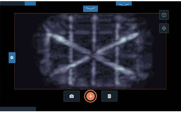
Flex Mode generates 3D GPR data with improved details without using grid pads or other grid layout technologies. Users should use Top Down View to scan a 120 cm × 60 cm (4 ft × 2 ft) area, and slice from top to bottom to rapidly see slab contents.
This example shows a Flex Mode scan in Top Down view. This dataset was collected with an average scan spacing of 2.5 cm (1 in), providing the resolution to distinguish two crossing conduits positioned above a rebar mat. Image Credit: Geophysical Survey Systems
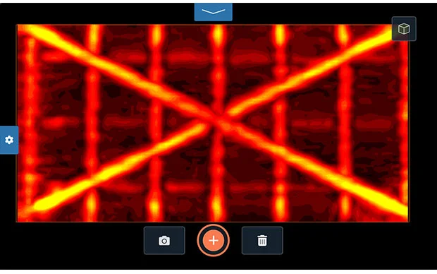
A New Dimension of Analysis
Flex Mode features a fully rotatable 3D Volume View, enabling users to view data from different angles. The feature provides a new dimension to field analysis by showing vertical relationships between targets of interest.
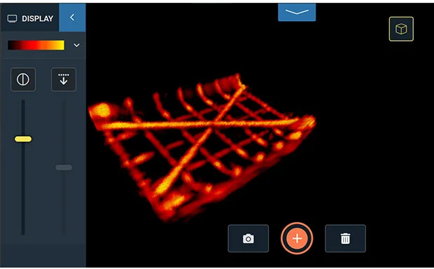
This example demonstrates the power of Flex Mode’s 3D Volume View. The 3D Volume model was rotated to further prove that the crossing conduits were installed above the rebar mat. Image Credit: Geophysical Survey Systems
Focus on the Area of Interest
Flex Mode enables capturing of both a broader context for targets and focusing only on the area of interest. Flex Mode helps scan a smaller area to refine the mark-out without reducing image quality or resolution.
This example shows a refined Flex Mode scan in Top Down view. This scan did not fill the entire 120 cm x 60 cm (4 ft x 2 ft) area, but it still revealed enough detail to set the stage for a traditional 2D mark out. Image Credit: Geophysical Survey Systems
Geolitix: Concrete Inspection Data
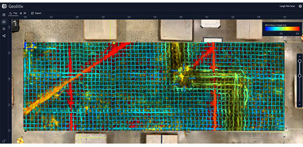
A large concrete grid, with 269 individual profiles totaling 4 GB, was collected with Flex NX and assembled in Geolitix. The data revealed highly detailed information about previous saw cuts and the wire mesh layout, and helped visualize a thicker concrete area with rebar or conduit running along the bottom of a dipping mesh section. Below the slab were multiple PVC pipes and a rodent burrow. The Multislice feature in Geolitix provided a full top-to-bottom view of the GPR slices by assigning different colors to targets at various depths. The resulting image served as a powerful mission-planning tool for subsequent cutting, coring, or drilling projects. Image Credit: Geophysical Survey Systems
Geolitix: Concrete Inspection Data
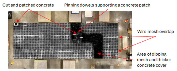
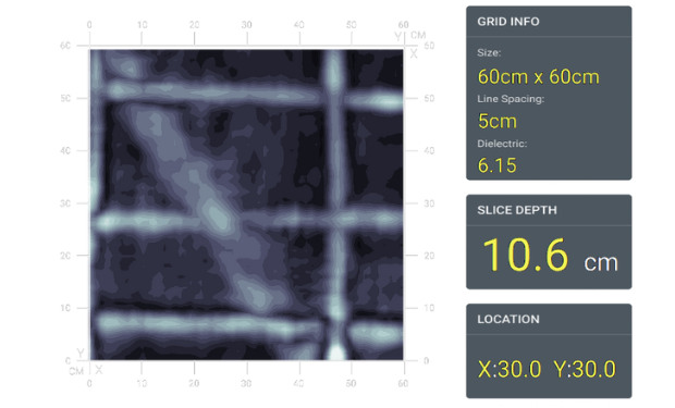
A large concrete grid, with 269 individual profiles totaling 4 GB, was collected with Flex NX and assembled in Geolitix. This top-down slice reveals stunning detail of the wire-mesh installation and previous saw cuts. It also shows an area where the mesh dips into a trench with a thicker concrete cover. Image Credit: Geophysical Survey Systems
Geolitix: Concrete Inspection Data
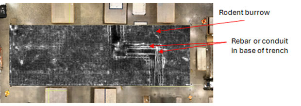
A large concrete grid, with 269 individual profiles totaling 4 GB, was collected with Flex NX and assembled in Geolitix. This top-down slice provides a detailed view of the base of the dipping mesh trench and shows rebar or conduit that should be avoided during cutting, coring, or drilling. Also imaged was a rodent burrow at the slab/sub-grade contact. Image Credit: Geophysical Survey Systems
Flex Grid
Flex Grid is used for more detailed analysis and visualization on either Flex NX or Flex LT. This grid-based data collection method also has an on-screen 3D visualization feature.
Data should be rotated to clearly understand the orientation of complex targets and features.
This data example shows reinforced concrete with deep rebar reflections in the upper section and a prominent, continuous response from a large electric conduit bank located beneath the rebar layer. Image Credit: Geophysical Survey Systems
Flex Grid
View top-down slices and position the on-screen cursor for improved precision on the markouts.
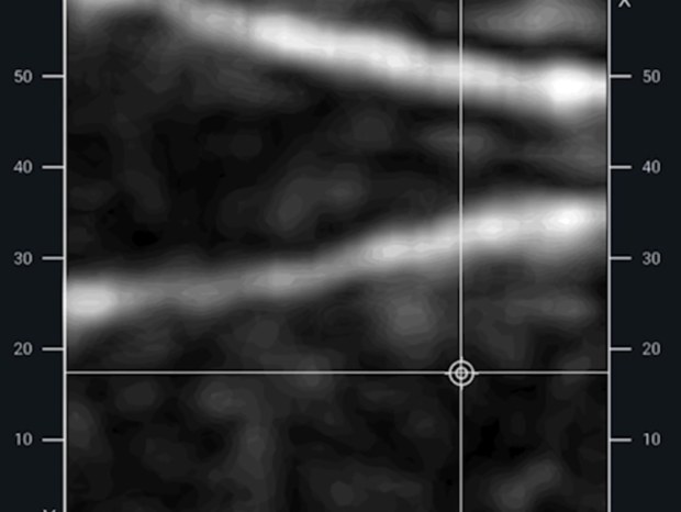
This image shows pan decking using the top-down Slice View. Image Credit: Geophysical Survey Systems
System Includes
- Flex NX® with adjustable handle
- Quick start documentation
- International: Dual-bay battery charger with AC adapter and four international plugs
- Two Lithium-ion batteries
- Safety wrist strap
- Two-year warranty
- US & Canada: Dual-bay battery charger
- Rugged Transit Case or Flex NX/LT Backpack
Specifications
Source: Geophysical Survey Systems
| . |
. |
| Storage |
200 GB |
| Operating Temperature |
-20 °C to +50 °C (-4 °F to +122 °F) |
| IP Rating |
IP65 |
| Power |
Lithium-ion battery |
| Dimensions |
25.3 × 13.2 × 18.9 cm (9.9 × 5.2 × 7.4 in) |
| Weight |
2.2 kg (4.9 lbs) including battery, 2.4 kg (5.3 lbs) including battery and handle |