Orton dilatometers are used to assess how temperature affects the dimensions of materials such as ceramics, glasses, carbon composites, metals, cermets, minerals, and polymers. During heating and cooling, the dilatometer measures both reversible and irreversible changes in length (expansion and shrinkage).
Samples are analyzed to determine firing ranges and schedules, evaluate thermal expansion ranges for glaze compatibility, and assess thermal expansion behavior for R&D, QC, or product certification purposes.
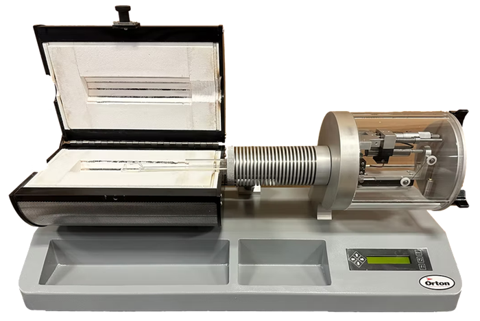
Image Credit: Orton Ceramic Foundation
Standard dilatometers from Orton are widely applied in ASTM E-228, C-372, and related testing methods to measure properties such as the Coefficient of Thermal Expansion (CTE), softening point, glass transition temperature, Curie point, crystalline and phase transformations, shrinkage, bloating, warping, sintering rate, isothermal creep, and stress relaxation.
System Description
A furnace (for a range of temperature ranges, including sub-ambient); a sample holder system (fused quartz or high alumina); a control/sample thermocouple; a sample displacement measuring system (probe rod and LVDT sensor); a spring tension or user-adjustable counterweighted pulley system to provide a contact load on the test sample; the Orton process controller for furnace control and data acquisition; and the Orton dilatometer software make up the standard Orton dilatometer.
Every Orton standard system is calibrated at the factory using a 1" platinum rod with a high-purity and thermal-expansion standard. Standard systems need 50/60 Hz power at either 120 VAC or 240 VAC. Standard options include split-tube furnaces for quick cooling or interchangeable furnaces for quick sample turnaround, over-temperature protection, and controlled atmosphere/vacuum components.
Horizontal Dilatometers (ASTM-E228)
The uniform temperature zone for the sample is the primary benefit of the horizontal system. A horizontal unit is used for most tests.
The sample is placed between the probe rod and the end of the sample container. The furnace is moved horizontally to cover the sample and the sample holder after the sample has been placed in the sample holder.
The probe rod connects to the displacement sensor assembly outside the furnace after extending from the end of the sample and passing through the sample holder tube. To maintain continuous contact with the sample even as it shrinks, the probe rod is under tension outside the furnace.
Principle of Operation
A sample specimen is positioned between the movable probing rod's end and the sample holder's end. The test sample is covered by the furnace, which is heated in accordance with a user-specified thermal cycle. The sample either shrinks away from the probe rod or expands against it as it heats and cools.
The sample and the probing rod are always in touch. The electronic displacement sensor (LVDT), which is situated outside of the heated chamber, receives the amount of sample movement from the probe rod. The LVDT continually transmits an electronic signal to the Orton process controller in response to changes in sample length.
Using the thermocouple temperature next to the sample, the process controller computes and stores the length-change data. For real-time monitoring and post-test analysis, the PLC and temperature data are downloaded to a separate computer system.
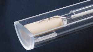
Image Credit: Orton Ceramic Foundation
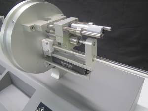
Image Credit: Orton Ceramic Foundation
Computer Analysis
Each Orton dilatometer comes with application software that must be installed on the user's computer in order to collect, save, and evaluate the generated data. The Orton Dilatometer software is designed for home PCs running Windows.
The software enables the test to be remotely planned and initiated for Standard Horizontal dilatometers. It can be used to analyze the data following the test cycle or to monitor the test in real time. After importing the data via the USB interface, the software saves it on the hard drive for analysis after testing.
Orton Standard Dilatometer Software
Every new standard dilatometer comes with an executable program called the Orton Standard Dilatometer Software (Version 8.0.x). The program interacts with the dilatometer after being loaded onto the user-provided PC system.
The software transmits the data to the dilatometer's process controller once the operator inputs the test settings into the user-friendly panels. During the test, the software gathers data from the dilatometer so the operator may keep an eye on it in real time.
The software generates a data file for post-test evaluation and analysis after the test is over. The operator has the option of seeing and analyzing the data files on the same computer or moving them to a different computer for separate viewing and analysis.
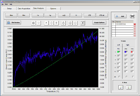
Image Credit: Orton Ceramic Foundation
Time, temperature, and percent linear change data are gathered, displayed, and stored in a binary file by the software. The PC monitor shows PLC data in time-based or temperature-based modes.
Data can be exported as an ASCII file or printed graphically or tabularly. Comparisons against temperature or time of up to six runs, zooming into a portion of the curve, displaying differential or alpha CTE curves, TG (between 400 and 850 °C) softening point temperatures, α-β quartz transition temperature, and coefficient of expansion computation for any temperature range are among the software's features.
The operator's PC running the English version of Windows OS can run the Orton Dilatometer Software, which comes on a CD or DVD.
Typical Specifications
Source: Orton Ceramic Foundation
| Model Number |
DIL 1410B |
DIL 1410STD |
DIL 1412STD |
DIL 1416STD |
DIL 1410C |
| |
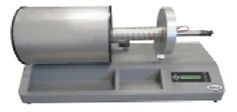 |
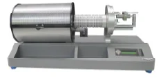 |
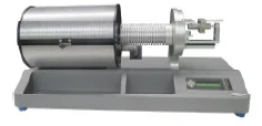 |
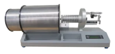 |
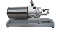 |
| Temperature Range |
RT to 1000 °C |
RT to 1000 °C |
RT to 1200 °C |
RT to 1600 °C |
RT to 1000 °C or -190 °C to +500 °C |
| Furnace |
Kanthal wire,
tube |
Kanthal wire,
split tube |
Kanthal wire,
split tube |
Silicon Carbide, tube |
Kanthal wire,
split tube |
| Thermocouple |
Type "N" |
Type "S" |
Type "S" |
Type "S" |
Type "N" |
Sample Holder and
Probe Rod |
Fused Quartz |
Fused Quartz |
High Alumina |
High Alumina |
Fused Quartz |
| Sample Size (max) |
50 mm long by
25 mm diameter |
50 mm long by
10 or 20 mm diameter |
50 mm long by
10 or 20 mm diameter |
50 mm long by
10 or 20 mm diameter |
50 mm long by
10 mm diameter |
| LVDT Displacement Range |
± 0.125 inch (± 3.17 mm) or ± 0.050 inch (± 1.27 mm) |
| Displacement Resolution 1 |
0.00000036 inch or 0.36 micro-inch (0.000009 millimeter or 0.009 microns) |
| PLC Resolution for a 1” Sample1 |
0.00009 % |
| Reproducibility Range 1 |
± 0.004 PLC
(± 1 μm / ± 40 μ-inches) |
± 0.004 PLC
(± 1 μm / ± 40 μ-inches) |
± 0.008 PLC
(± 2 μm / ± 80 μ-inches) |
± 0.008 PLC
(± 2 μm / ± 80 μ-inches) |
± 0.004 PLC
(± 1 μm / ± 40 μ-inches) |
| Contact Load |
Fixed -
113 grams |
Adjustable - minimum
4 gram weight |
Adjustable – minimum
4 gram weight |
Adjustable - minimum
4 gram weight |
Adjustable - minimum
4 gram weight |
| Temperature Control |
Orton User Programmable, 20-segment, PID Controller with Melting Point Protection |
| Heat-up Rate |
1 to 30 °C/minute
at 0.01 °C increments |
1 to 30 °C/minute
at 0.01 °C increments |
1 to 30 °C/minute
at 0.01 °C increments |
1 to 15 °C/minute
at 0.01 °C increments |
1 to 30 °C/minute
at 0.01 °C increments |
| Data Acquisition |
Orton On-board Computer (data stored in on-board computer at 1 °C increments, downloaded to independent PC system) |
| Data Analysis |
Orton Dilatometer Software Version 8.0.x (Requires English Language Version of Windows7/10) |
| Computer Interface |
USB Cable |
| Factory Calibration |
1” or 2” rod of high-purity platinum (platinum and copper for cryogenic system) |
| Secondary Calibration Sample |
high alumina included |
high alumina included |
high alumina included |
high alumina included |
high alumina and copper included |
Water Cooled Bulkhead (circulation system
not included) |
Not Available |
Available as Option |
Available as Option |
Available as Option |
Available as Option |
| Measuring Head Cover |
Not Available |
Included |
Included |
Included |
Included |
| Controlled Atmosphere |
Not Available |
Available as Option |
Available as Option |
Available as Option |
Included |
| Bench-top Footprint (open) Length x Depth x Height |
31” x 12” x 14”
(788 x 305 x 368 mm) |
31” x 12” x 14”
(788 x 305 x 368 mm) |
31” x 12” x 14”
(788 x 305 x 368 mm) |
31” x 12” x 14”
(788 x 305 x 368 mm) |
31” x 12” x 14”
(788 x 305 x 368 mm) |
| Transformer Footprint |
N/A |
N/A |
N/A |
14.5” x 9.25” x 9.62” (365 x 230 x 245 mm) |
N/A |
| Power Requirements |
120 or 240 VAC,
15 A, 50/60 Hz |
120 or 240 VAC,
15 A, 50/60 Hz |
120 or 240 VAC,
15 A, 50/60 Hz |
220-240 VAC,
20 A, 50/60 Hz |
120 or 240 VAC,
15 A, 50/60 Hz |
1 - contact Orton for a description and discussion of these specifications